2 axisgroup, Axisgroup – Lenze PLC Designer PLC-Designer (R2-x) SoftMotion User Manual
Page 20
L-force | PLC Designer - SoftMotion
The SoftMotion drive interface
Control configuration for SoftMotion
20
L
DMS 5.2 EN 03/2011 TD17
3.1.2
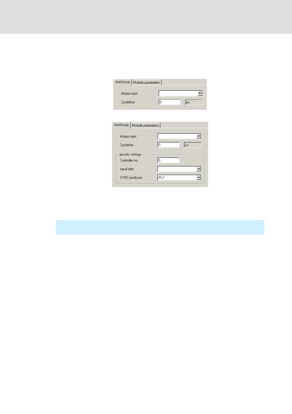
AxisGroup
Here the cyclic task where communication to the drives is effected and their cycle time is
specified.
Axis_IO_Group / Axis_Group_Dummy:
Axis_Group_CAN:
Apart from the specification of the baud rate, the controller number serves to define the
number of the CAN interface used (CAN1, CAN2, etc.). If a Logic bus is available (i. e. a CAN
master) it always occupies the CAN1 interface. Depending on the industrial PC used,
Motion buses can then be placed on the interfaces CAN2 ... CAN4.
For sync generators different methods can be selected for the synchronisation between
drives and the PLC:
PLC: Here the PLC is the synchronisation master. The user usually defines the motion
task as a cyclic task. This task calls the driver which immediately sends a sync telegram.
This method is the simplest, however it can cause problems if control systems with a
high variation and drives requiring a high accuracy of the sync telegram are used.
1. drive: This operating mode is not supported.
Sync device: This operating mode is not supported.
For this observe the information in the "CANopen control technology"
communication manual!