The modular system, 4×analog input / output, Stop – Lenze EPM−T9XX Modular system User Manual
Page 94: No input voltage in the resistance measuring range, Unused outputs remain unassigned
4×analog input / output
The modular system
4.20
L
4.20−2
EDSPM−TXXX−9.0−11/2009
(
Stop!
The module will be destroyed if the connected signals or encoders
do not match the set measuring range:
l
Max. 15 V input voltage in the voltage measuring range.
l
No input voltage in the resistance measuring range.
l
When the measuring range is changed, only assign the inputs
after the first gateway initialisation has been completed:
– During initialisation, the previous settings are still active.
Unsuitable input circuits may destroy the modules. Changes
will only become effective and permanently saved after
initialisation.
AI/AO 2/2x12BIT
+0
M0
+1
M1
Q0
M0
Q1
M1
F
L+
L
EPM – T330 1A. 10
0
1
2
3
4
5
6
7
8
9
10
1
.
D
A
D
A
µP
2
1
3
5
7
9
10
4
6
8
PES
PES
PES
PES
PES
PES
PES
PES
–
+
DC 24 V
(DC 20.4
… 28.8 V)
MUX
D
A
epm−t127
epm−t123
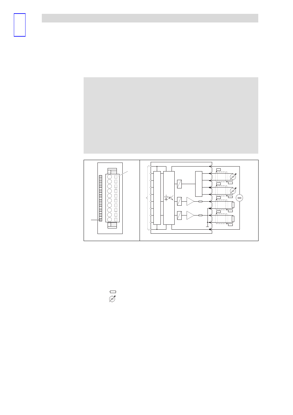
Fig. 4.20−2
Front view and connection of 4×analog input / output
0
Status display F; LED (red) is lit in
case of the following faults:
No external supply voltage
Wire breakage in the current
measuring range
1
Terminal strip assignment details
1
DC 24 V supply voltage
2
+ analog input E.0
3
− analog input E.0
4
+ analog input E.1
5
− analog input E.1
6
Analog output A.0
Input resistance of actuator
8
Analog output A.1
Sensor (voltage or current source)
7, 9 GND (reference potential for
analog signals)
PES HF shield termination through
large−surface connection to PE
10
GND (reference potential for
supply voltage)
.
Connection to backplane bus
l
Short−circuit unused inputs (connect positive and negative terminals) or
deactivate them by setting parameters.
l
Ensure correct polarity when connecting the actuators.
l
Unused outputs remain unassigned.
l
The module does not provide any auxiliary supply for sensors / actuators.
For information on how to connect an auxiliary supply, please see the
documentation for the sensors / actuators.
Status display and terminal
assignment