13 parameter setting via profibus−dp – Lenze EPM−T9XX Modular system User Manual
Page 460
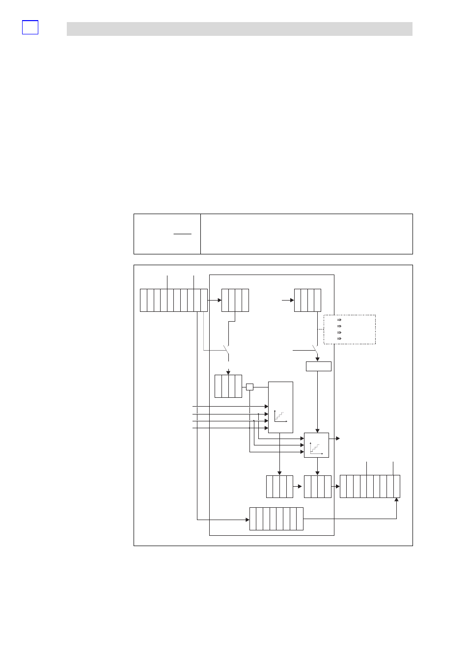
Parameterising 2/4xcounter module
Measuring the period (modes 17 and 19)
Parameter setting via PROFIBUS−DP
13.2
13.2.10
L
13.2−26
EDSPM−TXXX−9.0−11/2009
Mode 17:
The output OUT 0 is set to HIGH level when the
measuring process starts, and is
set to LOW level, when the measuring process is completed. The output OUT1
indicates the output signal of OUT0 in an inverted way.
Mode 19:
The output OUT 0 is set to HIGH level when the
counting process starts, and is set
to LOW level, when the counting process is completed. The output OUT1 indicates
the output signal of OUT0 in an inverted way.
T
+
n
f
ref
@ m
T
Average period
f
ref
Reference frequency (see figure "counter access")
m
Content, counter 1 (number of reference frequency pulses)
n
Number of CLK pulses in counter 0 (corresponds to Compare unless prematurely
terminated by a HIGH signal at input IN4 (STOP)
=1
dec
=128
dec
In2 (CLK)
In3 (Start)
In4 (Stop)
In1 (RES)
=
CLK
ref
counter 0
counter 1
Out0/Out1
Counter 0
Counter 0
Counter 1
Counter 1
Start Value
Dat
a
In
Control
Dat
a
In
Dat
a
In
Dat
a
In
S
tatus
Dat
a
In
Dat
a
In
Dat
a
In
Dat
a
In
Dat
a
In
Dat
a
In
Dat
a
In
Dat
a
In
Dat
a
In
Dat
a
In
Dat
a
In
Dat
a
In
Dat
a
In
0
0
0
1
1
1
2
2
2
3
3
3
4
4
5
5
6
6
7 8 9
7
Act. Value
Counter 0 Counter 1
Dat
a
Out
Dat
a
Out
Dat
a
Out
Dat
a
Out
Dat
a
Out
Dat
a
Out
Dat
a
Out
Dat
a
Out
Dat
a
Out
Dat
a
Out
Dat
a
Out
Dat
a
Out
S
tatus
S
tatus
Dat
a
Out
Dat
a
Out
Dat
a
Out
Dat
a
Out
0
8
0
1
1
2
2
3
3
4
4
5
5
6
6
7 8
7
compare
f
=
ref
f
=
f
=
f
=
ref
ref
ref
0
1
2
3
dec
dec
dec
dec
10 MHz
1 MHz
100 kHz
10 kHz
epm−t240
Fig. 13.2−32
Counter access of the 2/4xcounter in the modes 17 and 19
OUT signal
Computing the period
Counter access