The compact system, 16×dig. i/o compact (single−wire conductor) – Lenze EPM−T9XX Modular system User Manual
Page 127
16×dig. I/O compact (single−wire conductor)
The compact system
5.2
L
5.2−5
EDSPM−TXXX−9.0−11/2009
DI 8xDC24V
DIO/DO 4/4xDC24V 1A
L+
L+
.0
.0
.1
.1
.2
.2
.3
.3
.4
.4
.5
.5
.6
.6
.7
.7
F
F
1
1
2
2
3
3
4
4
5
5
6
6
7
7
8
8
9
9
10
10
L
PW
ER
RD
BA
ADR.
0
1
+
–
PE
X1
DC
24V
DI
8xDC24V
DIO 4xDC24V 1A
DO 4xDC24V 1A
X3
X4
EPM-T831 1A.10
0
2
1
3
epm−t051
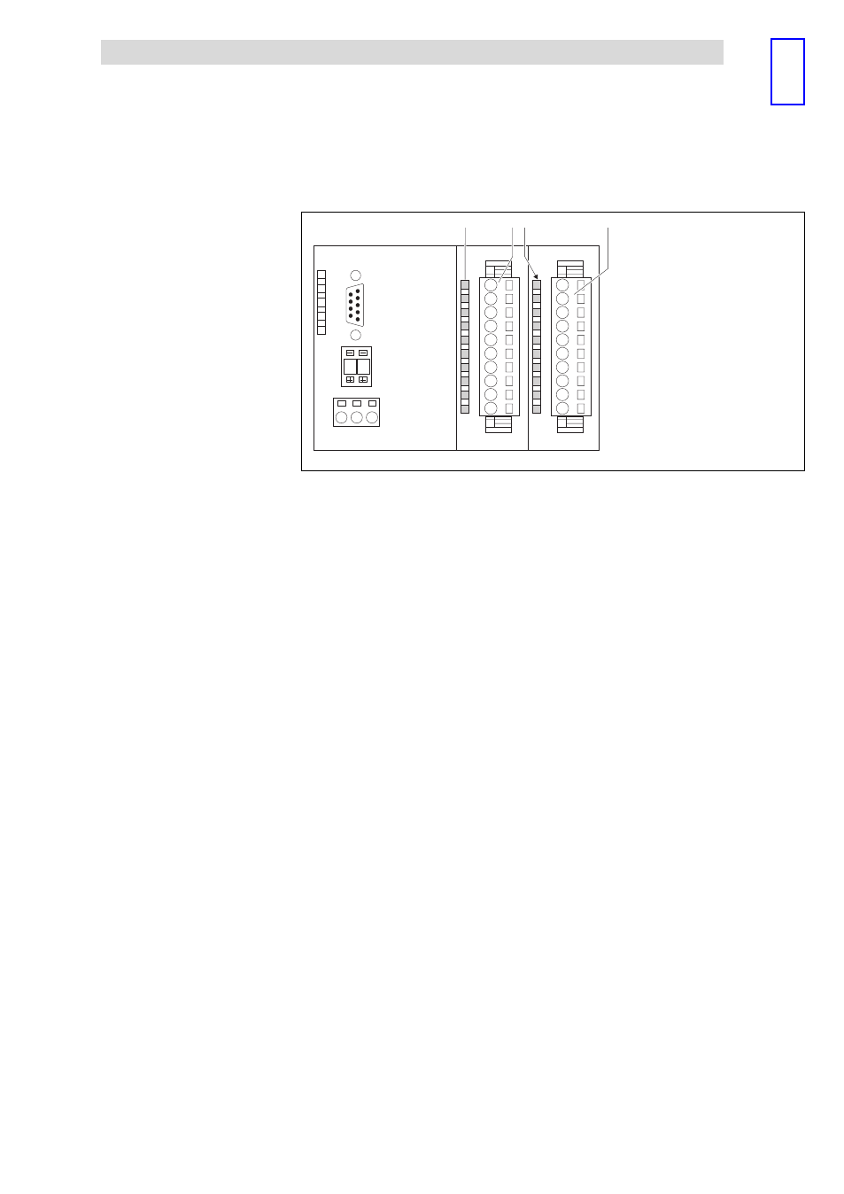
Fig. 5.2−4
Front view of 16×dig. I/O compact (single−wire conductor)
02
Status display for digital inputs / outputs at the terminal strips X3 and X4
L+
LED (yellow) is lit when the supply voltage is applied.
.0 ... .7
LED (green) is lit when the output is triggered and/or a HIGH
level is detected at the input
F
LED (red) is lit in case of overload, overheating, short−circuit
errors.
1
Terminal strip X3 assignment
X3/1
Not assigned
X3/2 ... X3/9
Digital inputs E.0 ... E.7
X3/10
GND (reference potential)
3
Terminal strip X4 assignment
X4/1
DC 24 V supply voltage
X4/2 ... X4/5
Digital inputs/outputs E/A.0 ... E/A.3
X4/6 ... X4/9
Digital outputs A.4 ... A.7
X4/10
GND (reference potential)
Status display and terminal
assignment