13 parameter setting via profibus−dp – Lenze EPM−T9XX Modular system User Manual
Page 422
Parameterising analog modules
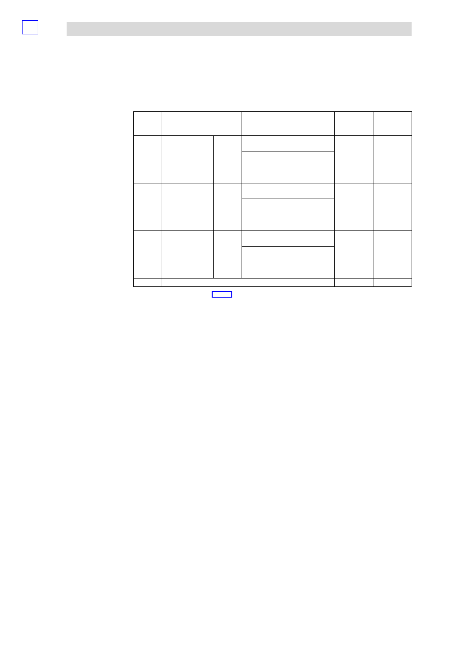
Signal functions of 4xanalog input
Parameter setting via PROFIBUS−DP
13.1
13.1.4
L
13.1−10
EDSPM−TXXX−9.0−11/2009
Paramete
r bytes
2/3/4/5
Tolerance
2)
Format
1)
Signal range
Signal function
5A
h
Voltage
measurement
±400 mV
−400
−4000
{1 mV}
{1
dec
}
+400
4000
S7
Two’s
complement
±0.1 % of the
final value
Min.
Limit
values
Max.
−474 mV
−4740
dec
+474 mV
4740
dec
5C
h
Current
measurement
±20 mA
−20.00
−20000
{0.01 mA}
{1
dec
}
+20.00
20000
S7
Two’s
complement
±0.05 % of
the final value
Min.
Limit
values
Max.
−23.70 mA
−23700
dec
+23.70 mA
+23700
dec
5D
h
Current
measurement
4 ... 20
mA
4.00
0
{0.01 mA}
{1
dec
}
20.00
16000
S7
Two’s
complement
±0.05 % of
the final value
Min.
Limit
values
Max.
0 mA
−4000
dec
+22.96 mA
+18960
dec
FF
h
Analog input deactivated
1)
Format of the input data (
¶ 13.1−6).
2)
Tolerance of the input range at an ambient temperature of 25 °C and 15 conversions/s. Sensor inaccuracies were
not considered.
3)
Transition resistances on contacts and cable resistances were not taken into consideration.
4)
Cold spot compensation must be effected externally.
5)
The cold spot must be compensated internally. The temperature of the terminal is taken into consideration.
Connect the conductors of the thermoelements directly to the terminal; if necessary, operate with thermoelement
extension cables.