The modular system, Profibus gateway – Lenze EPM−T9XX Modular system User Manual
Page 40
PROFIBUS Gateway
The modular system
4.3
L
4.3−2
EDSPM−TXXX−9.0−11/2009
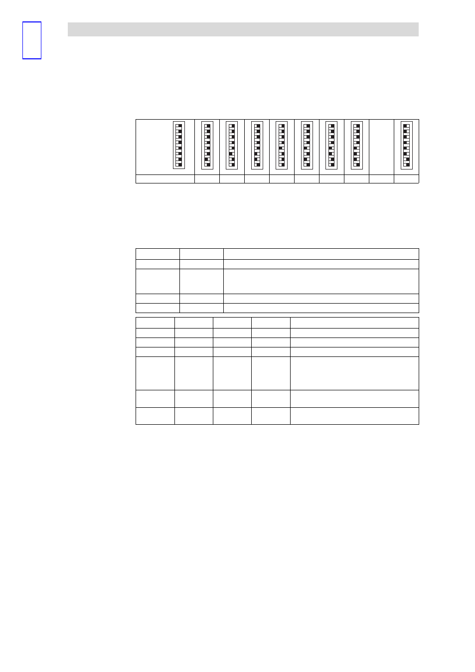
Coding
switch
64
32
16
8
4
2
1
–
1
0
...
Device address
1
2
3
4
5
6
7
...
125
l
Set the device address for the module with the coding switch.
– Allowed device addresses are 1 ... 125.
– Every device address must only be assigned once on the bus.
– Changes to the device address are only adopted when the supply voltage
is switched on again.
LED
Status
Meaning
PW (green)
on
Module supply voltage on
ER (red)
on
·
Incorrect data transmission on the backplane bus.
·
Internal fault
·
Lights up for approx. 1 second when the module is restarted
RD (green)
See table below
DE (green)
on
Error−free communication with PROFIBUS−DP
PW (green)
ER (red)
RD (green)
DE (green)
Meaning
on
on
off
off
Self−test and initialisation in progress
on
off
blinking
off
Self−test and initialisation was successful
on
blinking
off
off
Initialisation error
on
blinking
blinking
off
·
"ER" and "RD" blink asynchronously:
– Configuration faulty
·
"ER" and "RD" blink synchronously:
– Parameter settings faulty
on
off
on
on
The backplane bus cycle is quicker than the
PROFIBUS cycle
on
off
off
on
The backplane bus cycle is slower than the
PROFIBUS cycle
Setting the device address
Status displays