14 4×analog input, 4×analog input, The modular system – Lenze EPM−T9XX Modular system User Manual
Page 69
4×analog input
The modular system
4.14
L
4.14−1
EDSPM−TXXX−9.0−11/2009
4.14
4×analog input
The module 4×analog input has four analog inputs which can be parameterised
individually. The module assigns a total of eight bytes of input data in the process
image (two bytes per input). The analog inputs are isolated with regard to the
backplane bus.
)
Note!
The chapter "Parameter setting" describes how to parameterise
the module.
l
4 analog inputs
l
The inputs can be parameterised individually
l
Any unused inputs can be deactivated
l
The reference potentials (GND) of the analog inputs are electrically
separated from each other
l
The reference potentials may vary from each other by a voltage differential of
up to 5 V
l
Input ranges: Voltage, current, temperature, resistance
l
LED diagnostics display a wire breakage or overcurrent in the current
measuring range
0
1
2
epm−t015
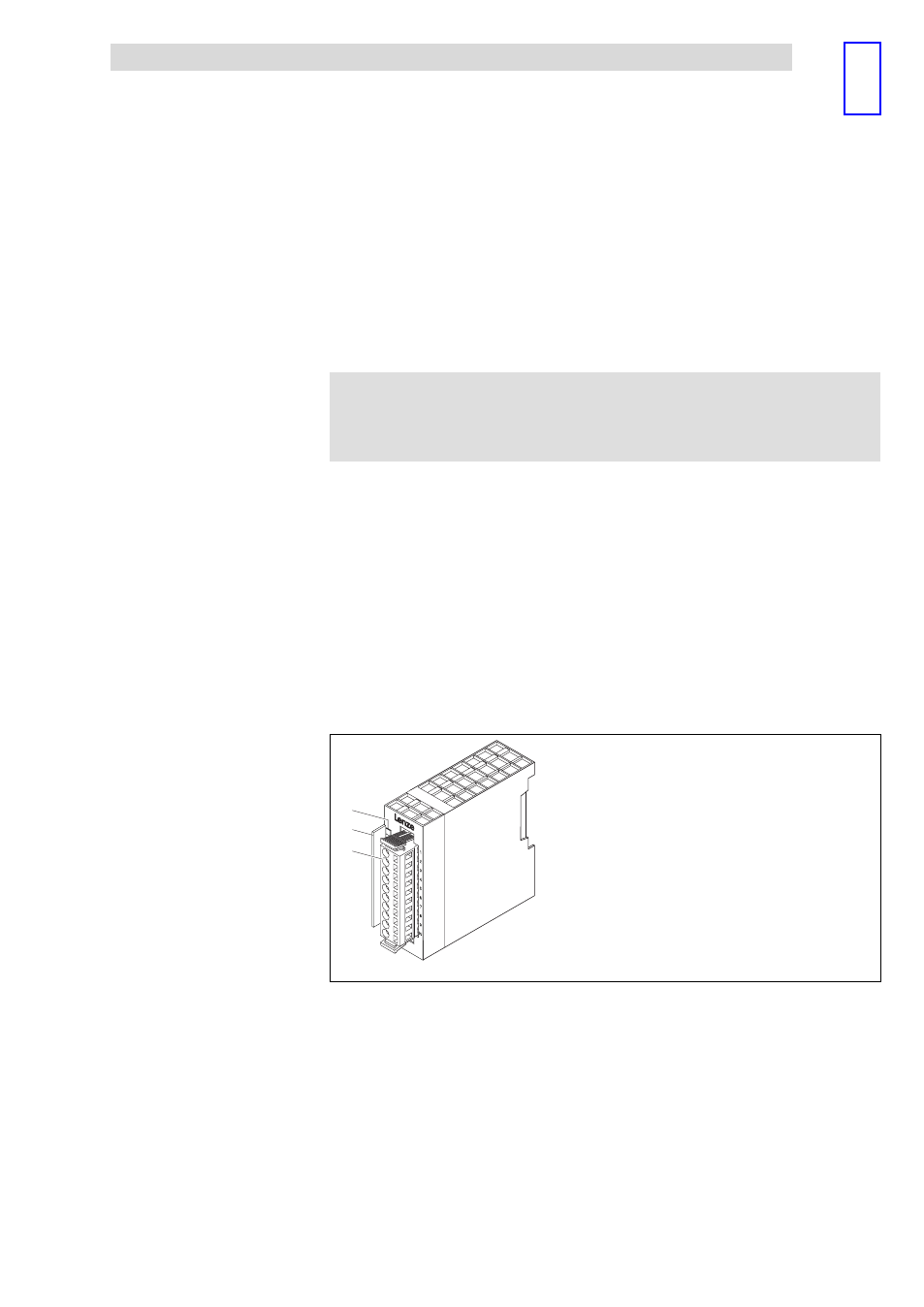
Fig. 4.14−1
Overview of 4×analog input
0
LED for status display
1
Bit address label card
2
Plug−in terminal strip
Description
Features
Overview