2 input data / output data, Input data / output data, 13 parameter setting via profibus−dp – Lenze EPM−T9XX Modular system User Manual
Page 438
Parameterising 2/4xcounter module
Input data / output data
Parameter setting via PROFIBUS−DP
13.2
13.2.2
L
13.2−4
EDSPM−TXXX−9.0−11/2009
13.2.2
Input data / output data
Gateway
Counter
.0
.1
.2
.3
.4
.5
.6
.7
1
2
3
4
5
6
7
8
9
L
L
10
Data to module
Control
S
tatus
Dat
a
In
Dat
a
In
Dat
a
In
Dat
a
In
Dat
a
In
Dat
a
In
Dat
a
In
Dat
a
In
0 1 2 3 4 5 6 7 8 9
Data from module
Dat
a
Out
Dat
a
Out
Dat
a
Out
Dat
a
Out
Dat
a
Out
Dat
a
Out
Dat
a
Out
Dat
a
Out
S
tatus
0 1 2 3 4 5 6 7 8
X1
PW
ER
RD
DE
DC
24V
+
-
EPM – T120 xx.xx
A
D
R.
64
32
16
8
4
2
1
–
1
0
epm−t249
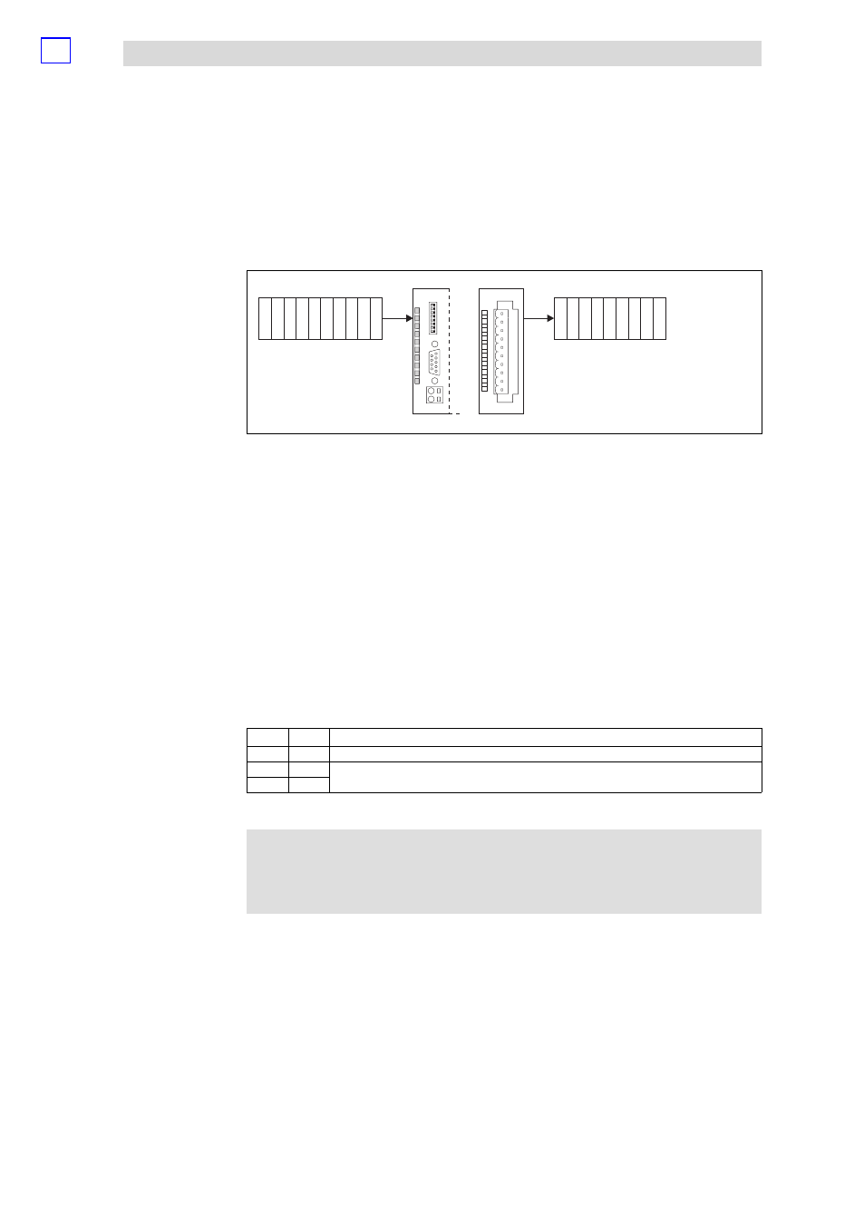
Fig. 13.2−1
Data input / output of 2/4xcounter
For the data input / data output, 10 bytes are available which are transmitted to the
counter or output by the counter.
8 bytes (byte 0 ... 7) of input data (Data In) for the specification of counter starting
values or comparison values.
Due to a level change in byte 9 (Control), the values are written into a counter
register. Each bit in byte 9 is assigned to a specific counter register word.
8 bytes (byte 0 ... 7) of output data (Data Out) for reading out the current count
values.
The behaviour of the counter, when the master module restarts (e.g. after changing
the parameter setting), can be controlled via byte 8 (status). The following
combinations are possible:
Bit 0
Bit 1
Description
1
0
Counter reading remanent on restart
0
1
Counter reading cleared on restart (Lenze setting)
1
1
A read access to byte 9 of the output data allows setting checks at any time.
)
Note!
Count values get lost when the mains supply is switched off/on;
they are not stored!
Input data
Control byte
Output data
Status byte