The compact system, 16×dig. i/o compact (single−wire conductor) – Lenze EPM−T9XX Modular system User Manual
Page 126
16×dig. I/O compact (single−wire conductor)
The compact system
5.2
L
5.2−4
EDSPM−TXXX−9.0−11/2009
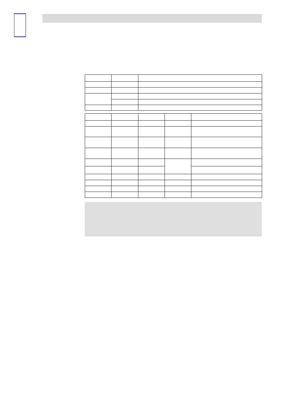
LED
Status
Meaning
PW (yellow)
on
Supply voltage is applied
ER (red)
on
Incorrect data transmission between microcontroller and digital inputs/outputs
RD (green)
on
Error−free data transmission between microcontroller and digital inputs/outputs
See table below
BA (yellow)
See table below
PW (yellow)
ER (red)
RD (green)
BA (yellow)
Meaning
on
off
blinking (1 Hz)
off
Self test and initialisation in progress
on
off
on
on
System bus (CAN)/CANopen in the
"Operational"state
on
off
on
blinking (1 Hz)
System bus (CAN)/CANopen in the
"Pre−Operational"state
on
off
on
blinking (10 Hz)
System bus (CAN)/CANopen in the
"Stopped"state
on
blinking (10 Hz)
on
on
blinking (1 Hz)
blinking (10 Hz)
System bus (CAN)/CANopen "Offline"state
on
blinking (1 Hz)
on
System bus (CAN)/CANopen "Warning"state
on
on
on
on
Error during RAM or EEPROM initialisation
on
blinking (1 Hz)
blinking (1 Hz)
blinking (1 Hz)
Baud rate setting mode active
on
blinking (10 Hz) blinking (10 Hz) blinking (10 Hz) Error during baud rate setting
on
off
blinking (1 Hz)
off
Address setting mode active
)
Note!
NMT telegrams for changing to the different states can be found in
the chapter "Networking via system bus (CAN)" or "Networking via
CANopen".
Status displays