Networking via profibus−dp, Diagnostics alarm messages – Lenze EPM−T9XX Modular system User Manual
Page 281
Diagnostics
Alarm messages
Networking via PROFIBUS−DP
10.6
10.6.3
L
10.6−7
EDSPM−TXXX−9.0−11/2009
)
Note!
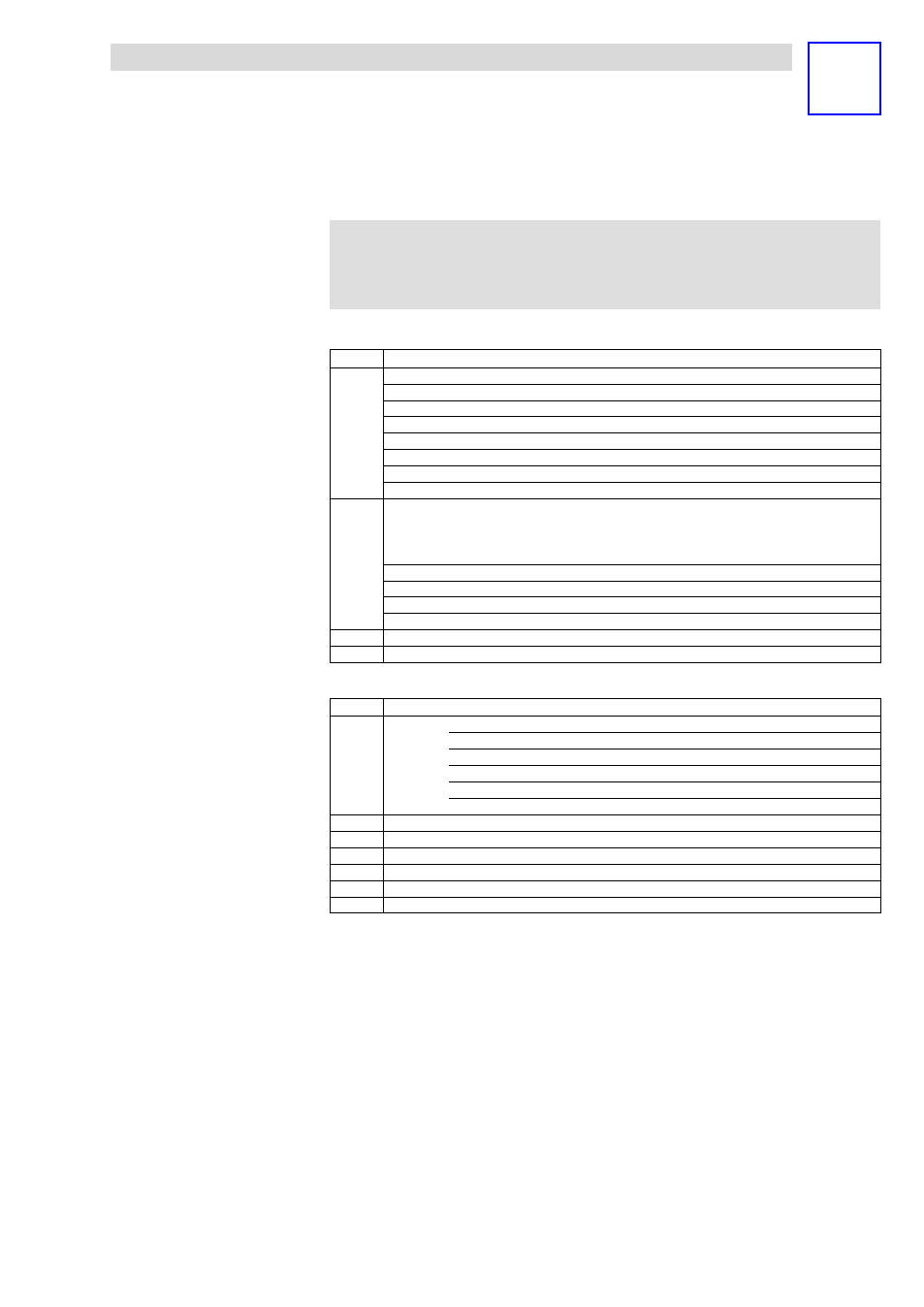
Starting from byte 5, 16 bytes of additional alarm information are
added.
Bytes 5 to 8 correspond to the CPU diagnostic data record 0:
Byte
Assignment
Byte 5
Bit 0
1
Module error, an error was detected
Bit 1
1
Internal error in module
Bit 2
1
External error, module cannot be addressed
Bit 3
1
Channel error in the module
Bit4
1
No load voltage supply
Bit 5
1
No front connector
Bit 6
1
Module is not parameterised
Bit7
1
Parameter setting error
Byte 6
Bit 3 ... 0
Module class
1111
Digital module
0101
Analog module
1000
Counter module
Bit4
1
Channel information available
Bit 5
1
User information available
Bit 6
0
Reserved
Bit7
0
Reserved
Byte 7
Bit 7 ... 0
Reserved
Byte 8
Bit 7 ... 0
Reserved
Bytes 9 to 20 correspond to the CPU diagnostic data record 1:
Byte
Assignment
Byte 9
Bit 7 ... 0
01110000
Digital module with inputs
01110001
Analog module with inputs
01110010
Digital module with outputs
01110011
Analog module with outputs
01110100
Analog module with inputs and outputs
01110101
Counter module
Byte 10
Bit 7 ... 0
Length of the channel−specific diagnostics
Byte 11
Bit 7 ... 0
Number of channels per module
Byte 12
Bit 7 ... 0
Position (channel) of the diagnostic event
Byte 13
Bit 7 ... 0
Diagnostic event for channel/channel group 0 (see module description)
...
...
...
Byte 19
Bit 7 ... 0
Diagnostic event for channel/channel group 7 (see module description)