The modular system, 4×analog input, Stop – Lenze EPM−T9XX Modular system User Manual
Page 71
4×analog input
The modular system
4.14
L
4.14−3
EDSPM−TXXX−9.0−11/2009
(
Stop!
The module will be destroyed if the connected signals or encoders
do not match the set measuring range:
l
Max. 15 V input voltage in the voltage measuring range.
l
No input voltage in the resistance measuring range.
l
When the measuring range is changed, only assign the inputs
after the first gateway initialisation has been completed:
– During initialisation, the previous settings are still active.
Unsuitable input circuits may destroy the modules. Changes
will only become effective and permanently saved after
initialisation.
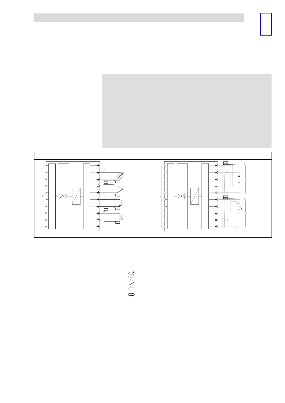
Two−wire connection
Four−wire connection
2
1
3
5
7
9
10
4
6
8
J
.
D
A
µP
MUX
PES
PES
PES
PES
PES
PES
PES
PES
D
A
µP
MUX
9
10
+U
+U
-U
-U
I
I
I
I
8
7
6
5
4
3
2
1
J
1
0
PES
PES
.
epm−t036
epm−t033
Fig. 4.14−3
Sensor connection
0
Analog input E.0
1
Analog input E.2
.
Connection to backplane bus
PES
HF shield termination through large−surface connection to PE
Sensor:
Voltage or current source
Thermal element
Resistor
J
Resistor, temperature−dependent
l
Short−circuit unused inputs (connect positive and negative terminals) or
deactivate them by setting parameters.
l
The module does not provide any auxiliary supply for sensors / actuators.
For information on how to connect an auxiliary supply, please see the
documentation for the sensors / actuators.
Connection