The modular system, 2/4×counter – Lenze EPM−T9XX Modular system User Manual
Page 100
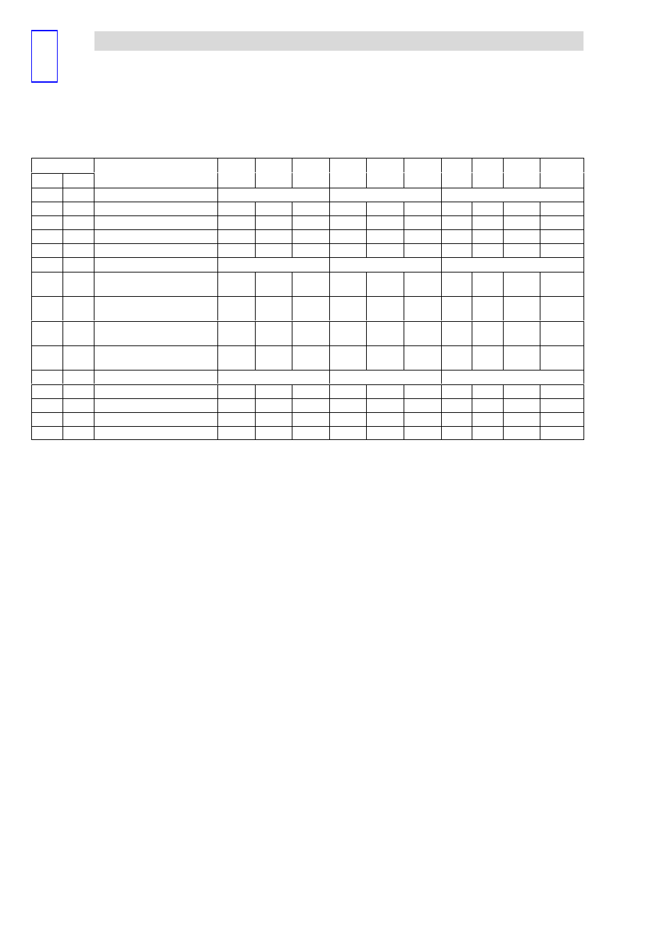
2/4×counter
The modular system
4.21
L
4.21−4
EDSPM−TXXX−9.0−11/2009
Mode of
Compare
Load
Auto
Reload
OUT1
OUT0
IN6
IN5
IN4
IN3
IN2
IN1
Function
[h]
Compare
Load
Auto
Reload
OUT1
OUT0
IN6
IN5
IN4
IN3
IN2
IN1
Function
[dec]
2 counters
0
1
1B
h
27
32−bit counter
G/RES
û
CLK
DIR
G/RES
û
CLK
DIR
·
·
–
–
1C
h
28
Encoder 1 edge
G/RES
û
A
B
G/RES
û
A
B
·
·
–
–
1D
h
29
Encoder 2 edges
G/RES
û
A
B
G/RES
û
A
B
·
·
–
–
1E
h
30
Encoder 4 edges
G/RES
û
A
B
G/RES
û
A
B
·
·
–
–
2 counters
0
1
1F
h
31
2 × 32−bit counters
(counting direction up)
RES
û
CLK
GATE
RES
û
CLK
GATE
·
·
–
ü
20
h
32
2 × 32−bit counters
(counting direction down)
RES
û
CLK
GATE
RES
û
CLK
GATE
·
·
–
ü
21
h
33
2 × 32−bit counters
(counting direction up)
RES
û
CLK
GATE
RES
û
CLK
GATE
·
·
ь
ь
22
h
34
2 × 32−bit counters
(counting direction down)
RES
û
CLK
GATE
RES
û
CLK
GATE
·
·
ь
ь
2 counters
0
1
23
h
35
32−bit counter
GATE
CLK
DIR
GATE
CLK
DIR
·
·
–
–
24
h
36
Encoder 1 edge
GATE
A
B
GATE
A
B
·
·
–
–
25
h
37
Encoder 2 edges
GATE
A
B
GATE
A
B
·
·
–
–
26
h
38
Encoder 4 edges
GATE
A
B
GATE
A
B
·
·
–
–
·
Digital output can signal an event
ü
Function available.
–
No function / function not available
A
Encoder signal A
Auto Reload
"Auto Reload" causes the counter to accept a preset value as soon
as the counter content matches the Compare register content.
B
Encoder signal B
Compare Load You may use "Compare Load" to specify a counter limit value to
trigger an output when reached or to restart the counters via Auto
Reload.
CLK
Clock signal of a connected encoder
HIGH level starts and / or stops the counting process
DIR
Indicates counting direction depending on signal level
LOW: Upcounter
HIGH: Downcounter
GATE
Gate signal is level−triggered
HIGH: Pulses are measured
G/RES
û
Gate signal is level−triggered and reset signal is edge−triggered
HIGH: Pulses are measured
LOW−HIGH edge: Deletes one or both counters
PULSE
The pulse width of the supplied signal is measured with an internal
time base
RES
Reset signal is level−triggered
HIGH: Deletes one or both counters
RES
û
Reset signal is edge−triggered
LOW−HIGH edge: Deletes one or both counters
START
Start signal is edge−triggered
STOP
Stop signal is edge−triggered