Appendix, Index table – Lenze EPM−T9XX Modular system User Manual
Page 527
Index table
Appendix
15.1
L
15.1−13
EDSPM−TXXX−9.0−11/2009
Index
Important
Possible settings
Name
Selection
Lenze
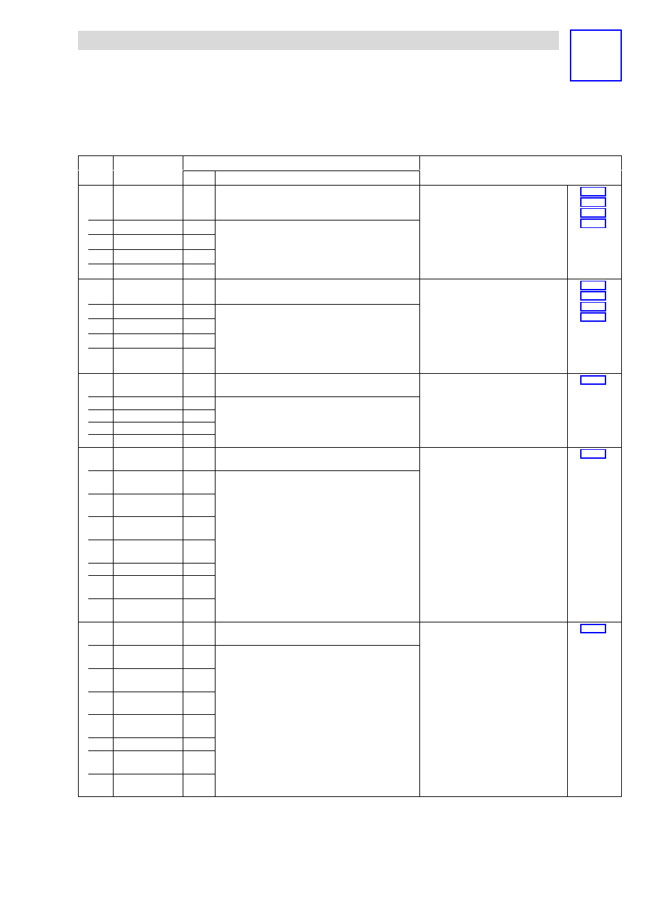
I3010
h
¿
Config
analog/counter
module 16
00000000
h
{1
h
}
FFFFFFFF
h
Configuration of analog module,
2/4xcounter module, SSI interface module
or 1xcounter/16xdigital input module on
slot 16
·
I3010
h
can only be accessed via Global
Drive Control (GDC). Use I3401
h
in
CoDeSys programming systems.
·
I3010
h
is only available for the modular
system.
^ 12.3−1
^ 12.4−1
^ 12.5−1
^ 12.6−1
1
0
h
2
0
h
3
0
h
4
0
h
I3401
h
¿
Config analog /
counter module
0
{1
h
}
255 Configuration of analog module,
2/4xcounter module, SSI interface module
or 1xcounter/16xdigital input module
·
I3401
h
can only be accessed via
CoDeSys programming systems. The
index is not available in Global Drive
Control (GDC).
·
I3401
h
is only available for the modular
system.
^ 12.3−1
^ 12.4−1
^ 12.5−1
^ 12.6−1
1 1st mapped object
0
h
2 2nd mapped object
0
h
... ...
0
h
64 64th mapped
object
0
h
I4000
h
Digital counter
value 16DI/1C
0
{1}
255 Display only
·
Module 1×counter/ 16×digital input
·
Count display
^ 12.6−1
1 Module 1
2 Module 2
... ...
8 Module 8
I4001
h
Digital input
16DI/1C
0
{1}
255 Display only
·
Module 1×counter/ 16×digital input
·
Display of digital input states
^ 12.6−1
1 Module 1
Bits 0 ... 7
2 Module 1
Bits 8 ... 15 %
3 Module 2
Bits 0 ... 7
4 Module 2
Bits 8 ... 15 %
... ...
15 Module 8
Bits 0 ... 7
16 Module 8
Bits 8 ... 15 %
I4002
h
*
Change polarity
input 16DI/1C
0
{1}
255 Module 1×counter/ 16×digital input
·
Setting of digital input polarity:
– Bit x = 0: Input HIGH active
– Bit x = 1: Input LOW active
^ 12.6−1
1 Module 1
Bits 0 ... 7
2 Module 1
Bits 8 ... 15 %
3 Module 2
Bits 0 ... 7
4 Module 2
Bits 8 ... 15 %
... ...
15 Module 8
Bits 0 ... 7
16 Module 8
Bits 8 ... 15 %