3 encoder (mode 0), Encoder (mode 0), 13 parameter setting via profibus−dp – Lenze EPM−T9XX Modular system User Manual
Page 498
Parameterising 1xcounter/16xdigital input module
Encoder (mode 0)
Parameter setting via PROFIBUS−DP
13.4
13.4.3
L
13.4−4
EDSPM−TXXX−9.0−11/2009
13.4.3
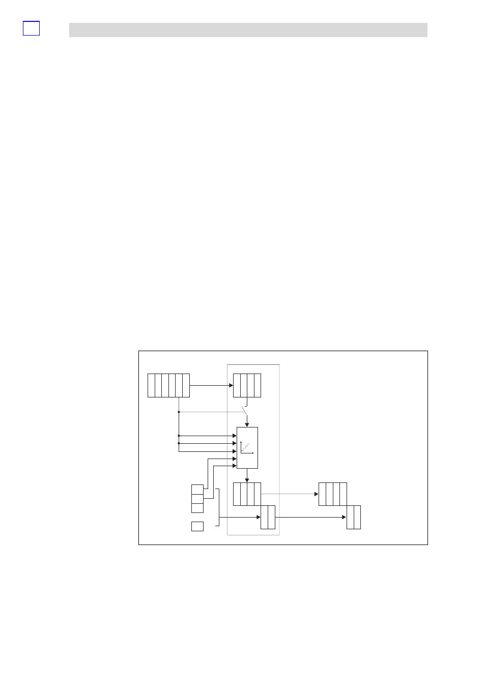
Encoder (mode 0)
In the mode 0, the rising and falling edges of signal A and B are evaluated. The
counter can be pre−assigned with a starting value via the Rx PDO.
The counting range lies between 0 and +4.294.967.295. As soon as the upper limit
(when counting upwards) has been reached, the count value jumps to the lower
count limit. The moment, the lower count limit (when counting downwards) has
been reached, the count value jumps to the upper count limit.
A HIGH level in byte 4 (Control), bit 3 (Clear) sets the counter to zero.
When bit 2 (Load) changes from LOW to HIGH in byte 4 (Control), the counter is
pre−assigned with the starting value from byte 0 to 3 (Data In).
The software gate which releases the counting process, is opened, when bit 0
(Start) in the byte 4 (Control) has HIGH level. It is closed as soon as bit 1 (Stop) has
HIGH level.
With the software gate open: Every rising or falling edge of signal A (E.0) and B (E.1)
increments or decrements the count value. The counting direction depends on
which signal is leading.
Act. value
counter
Start value counter
Data to module
Data from module
Dat
a
Out
E.0...E.7
E.0...E.7
Dat
a
Out
E.8...E.15
E.8...E.15
Dat
a
Out
Dat
a
Out
Dat
a
In
Dat
a
Out
Dat
a
Out
Dat
a
Out
Dat
a
Out
Dat
a
In
Dat
a
In
Dat
a
In
Dat
a
In
Dat
a
In
Dat
a
In
Control
Dat
a
In
Ref.
Freq.
0
0
0
0
A
B
Start=1
dec
Load=4
dec
Stop=2
dec
Clear=8
dec
1
1
1
1
2
2
2
2
3
3
3
3
4
4
4
5
5
5
:
E.0
E.1
E.2
E.15
epm−t255
Fig. 13.4−3
Counter access of 1xcounter/16xdigital input in the mode 0
Clear signal
Load signal
Start/stop signal
A/B signal
Counter access