2 input data / output data, Input data / output data, 13 parameter setting via profibus−dp – Lenze EPM−T9XX Modular system User Manual
Page 496
Parameterising 1xcounter/16xdigital input module
Input data / output data
Parameter setting via PROFIBUS−DP
13.4
13.4.2
L
13.4−2
EDSPM−TXXX−9.0−11/2009
13.4.2
Input data / output data
L
X1
PW
ER
RD
DE
DC
24V
+
-
EPM – T120 xx.xx
A
D
R.
64
32
16
8
4
2
1
–
1
0
Gateway
Counter/Dig In
.0
.1
.2
.3
.4
.5
.6
.7
1
2
3
4
5
6
7
8
9
L
10
Data to module
0 1 2 3 4 5
Dat
a
In
Dat
a
In
Dat
a
In
Control
Dat
a
In
Ref.
Freq.
Data from module
Dat
a
Out
E.0...E.7
Dat
a
Out
E.8...E.15
Dat
a
Out
Dat
a
Out
0 1 2 3 4 5
:
E.0
E.1
E.15
epm−t253
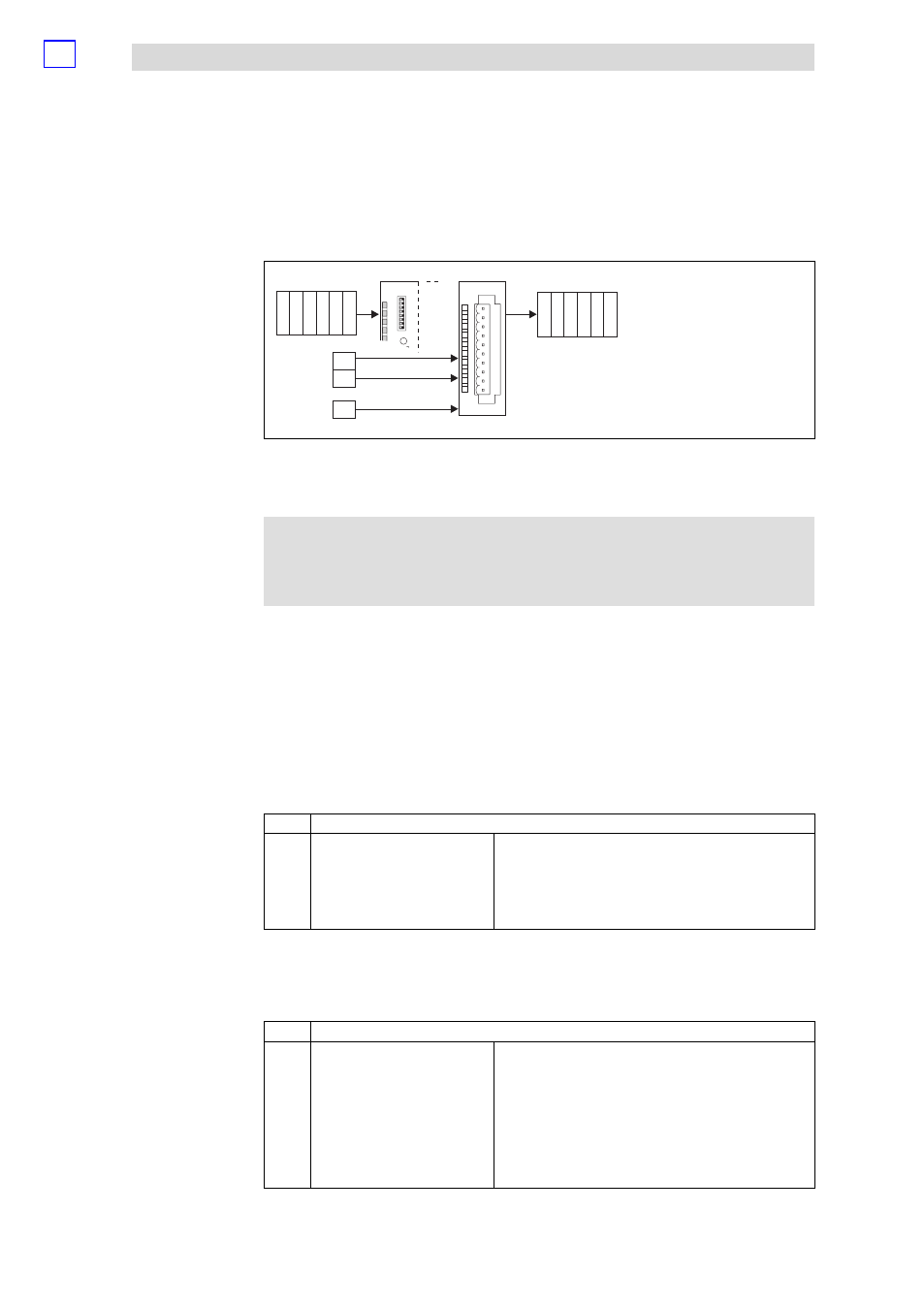
Fig. 13.4−1
Data input / data output 1xcounter/16xdigital input
For the data input / data output, 6 bytes are available which are transmitted to the
counter or output by the counter.
)
Note!
Input and output data are lost when the supply voltage is
disconnected; they are not saved!
The inputs E.0 and E.1 are used as counter inputs and digital inputs.
The counter starting value is located in bytes 0 to 3 (Data In). If a starting value is
loaded, the counter counts up or down, starting with this value.
The counting range lies between 0 and +4.294.967.295. As soon as the upper limit
(when counting up) has been reached, the count value jumps to the lower count
limit. The moment, the lower count limit (when counting down) has been reached,
the count value jumps to the upper count limit.
The counter is controlled via byte 4 (control). It is assigned as follows:
Byte
Assignment
4
Control byte
Bit 0
1 = Start counter (software gate is open)
1)
Bit 1
1 = Stop counter (software gate is closed)
1)
Bit 2
1 = Counter is loaded with starting value / comparison
value
Bit 3
1 = Count value is deleted
Bit 4 ... 7
Reserved
1)
If start bit and stop bit = HIGH, "stop" is active. If both bits are LOW, the state of the bit that has been set last, is
active.
Via byte 5 the reference frequency for the modes 3 (frequency measurement) and
4 (period measurement) can be set. It is assigned as follows:
Byte
Assignment
5
Reference frequency
00
h
16 MHz
01
h
8 MHz
02
h
4 MHz
03
h
1 MHz
04
h
100 kHz
05
h
10 kHz
06
h
1 kHz
07
h
100 Hz
08
h...
FF
h
not permissible
Input data