1 parameterising analog modules, 1 parameter data, Parameterising analog modules – Lenze EPM−T9XX Modular system User Manual
Page 413: Parameter data, 13 parameter setting via profibus−dp, Parameterising analog modules parameter data, Stop
Parameterising analog modules
Parameter data
Parameter setting via PROFIBUS−DP
13.1
13.1.1
L
13.1−1
EDSPM−TXXX−9.0−11/2009
13.1
Parameterising analog modules
13.1.1
Parameter data
(
Stop!
The modules are not protected against wrong parameter settings
by the hardware. They will be destroyed if the signals or encoders
connected do not match the measuring range set:
l
Max. 15 V input voltage in the voltage measuring range.
l
No input voltage in the resistance measuring range.
l
When the measuring range is changed, only assign the inputs
after the first gateway initialisation has been completed:
– During initialisation, the previous settings are still active.
Unsuitable input circuits may destroy the modules. Changes
will only become effective and are permanently saved after
initialisation.
l
For a 4×analog input module, 10 bytes of parameter data are available. The
following are defined via the parameter data
– The signal function for each input (current measurement, voltage
measurement, temperature measurement etc.),
– The module error behavior,
– The conversion speed.
l
The module can be parameterised with the configuration tool or via slot and
index.
– To set the parameters via slot and index, the function blocks SFB 52 (read)
and SFB 53 (write) are required.
(
¶ 10.5−3)
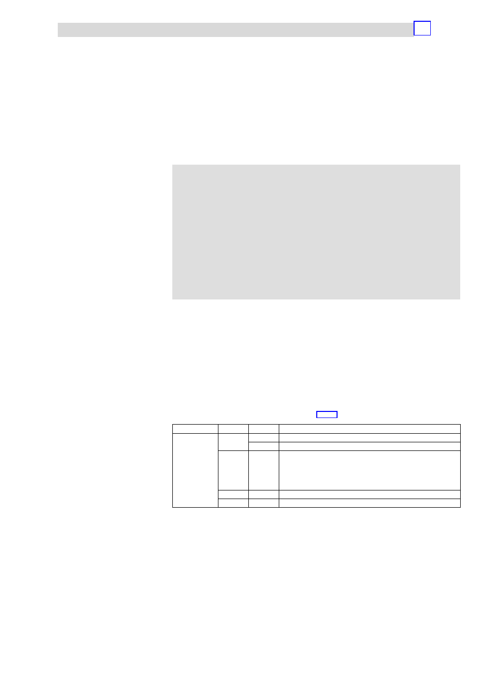
Slot number
Index
Access
Description
1 ... 32
00
h
R
Read out diagnostic data record 0
W
Write parameters to the module
01
h
R
The corresponding diagnostic data record of the electronic module can be
read out via the index.
·
Example:
– Index 01
h
: read out diagnostic data record 1
– Index 02
h
: read out diagnostic data record 2
F1
h
R
Read out the module parameters
F2
h
R
Read out the process image of the module
R = read
W = write
4xanalog input module