2 can gatewayeco, Can gatewayeco, The modular system – Lenze EPM−T9XX Modular system User Manual
Page 35: Up to 8 modules can be connected to a can gateway, Address and baud rate setting via dip switch, Led for status display
CAN GatewayECO
The modular system
4.2
L
4.2−1
EDSPM−TXXX−9.0−11/2009
4.2
CAN GatewayECO
The CAN GatewayECO is the interface between the process level and the master
bus system. The control signals at the process level are transmitted by the
electronic modules. These modules are connected with the CAN Gateway via the
backplane bus (EPM−T9XX). CAN Gateway and the connected electronic modules
communicate via the backplane bus. A configuration is not required.
l
Up to 8 modules can be connected to a CAN Gateway
l
Integrated power supply unit for the internal voltage supply and the voltage
supply of the connected electronic modules
– Power supply unit is fed via an external DC voltage source
l
Only supports the electronic module types EPM−T2xx and EPM−T3xx
l
Connection to the system bus (CAN) / CANopen via a 9−pole Sub−D plug
l
Address and baud rate setting via DIP switch
l
The baud rate is stored permanently in an EEPROM in the module
l
LED for status display
PW
ER
RD
BA
DC
24V
+
-
1
2
X1
EPM
– T1
11
xx.xx
0
1
2
3
A
D
R.
64
32
16
8
4
2
1
L/C
1
0
epm−t225
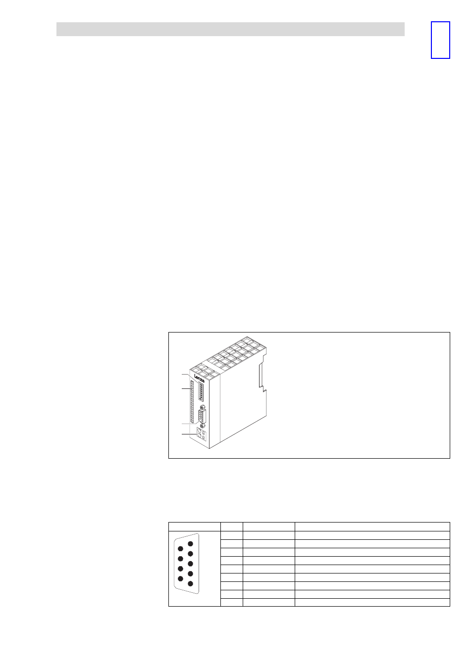
Fig. 4.2−1
Overview of Can GatewayECO
0
Coding switch to set address and baud rate
1
LED for status display
2
9−pin Sub−D plug for the connection to the fieldbus
3
External voltage supply connection
View
Pin
Assignment
Explanation
1
2
3
4
5
6
7
8
9
1
Not assigned
−
2
CAN−LOW
Data line
3
CAN−GND
Data ground
4
Not assigned
−
5
Not assigned
−
6
Not assigned
−
7
CAN−HIGH
Data line
8
Not assigned
−
epm−t023
9
Not assigned
−
Description
Features
Overview
Connecting system
bus (CAN)/CANopen