4 parameterising 2/4xcounter module, 1 parameter data, Parameterising 2/4xcounter module – Lenze EPM−T9XX Modular system User Manual
Page 321: Parameter data, Parameterising 2/4xcounter module parameter data, Stop
Parameterising 2/4xcounter module
Parameter data
Parameter setting via system bus (CAN) / CANopen
12.4
12.4.1
L
12.4−1
EDSPM−TXXX−9.0−11/2009
12.4
Parameterising 2/4xcounter module
12.4.1
Parameter data
The operating mode of the 2/4xcounter (e.g. 2 x 32−bit counter or 4 x 16−bit
counter) can be determined by assigning each channel (counter 0 and counter 1)
a mode via the parameter data.
(
Stop!
Depending on the mode setting, the terminal assignment of the
counter module changes!
For the 2/4xcounter two bytes of parameter data are available which are assigned
via SDOs.
Parameter setting via Global Drive Control (GDC):
Depending on the plug−in station, the counter module is parameterised via the
indices 3001
h
... 3010
h
(max. 4 counter modules). The parameter data are stored
in the subindex 1.
Parameter setting via CoDeSys:
The max. 4 counter modules are addressed via index I3401
h
. The parameter data
are assigned in the subindices 1 ... 64 (4 bytes per subindex). The counter module
assigns 1 subindex.
Index
Subindex
1
00
h
00
h
00
h
00
h
Byte 1
Byte 0
I3xxx
h
epm−t062
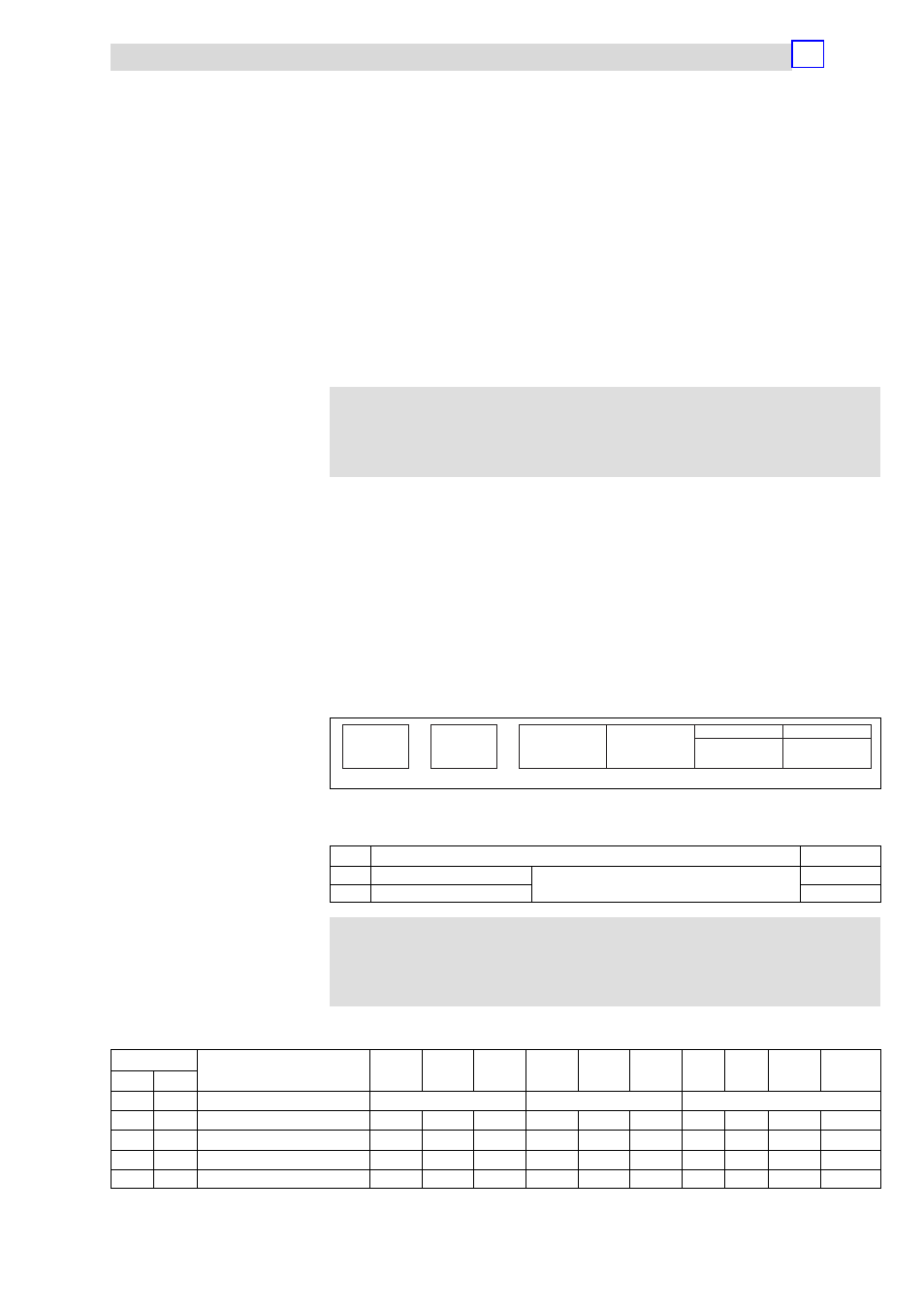
Fig. 12.4−1
Display of the parameter data of 2/4xcounter
The parameter data follow the assignment below:
Byte
Assignment
Lenze setting
0
Mode, counter 0
Selecting the modes
00
h
1
Mode, counter 1
00
h
)
Note!
Store changed parameters in the EEPROM via index I2003
h
. The
settings are maintained after switching off the supply voltage.
Counter mode overview
Mode of
Function
IN1
IN2
IN3
IN4
IN5
IN6
OUT0
OUT1
Auto
Reload
Compare
Load
[h]
[dec]
2 counters
0
1
00
h
0
32−bit counter
RES
CLK
DIR
RES
CLK
DIR
·
·
–
–
01
h
1
Encoder 1 edge
RES
A
B
RES
A
B
·
·
–
–
03
h
3
Encoder 2 edges
RES
A
B
RES
A
B
·
·
–
–
05
h
5
Encoder 4 edges
RES
A
B
RES
A
B
·
·
–
–