Networking via system bus (can) – Lenze EPM−T9XX Modular system User Manual
Page 184
Transmitting process data
Data transmission between I/O system IP20 and controller
Networking via system bus (CAN)
8.3
8.3.8
L
8.3−10
EDSPM−TXXX−9.0−11/2009
The planned solution is a modular system with the following modules:
I/O system IP20
Modular system
Number
modules
Required PDOs
PDO−Rx
PDO−Tx
8×digital input / output
1
1/8
1/8
8×digital input
1
–
1/8
4×analog input
1
1
–
Sum
3
9/8
2/8
For exchanging the process data, the 8200 vector makes enough PDOs available:
Frequency inverter
Available PDOs
PDO−Rx
PDO−Tx
8200 vector
2
2
8.3.8
Data transmission between I/O system IP20 and controller
l
The basic identifiers of PDO1−Rx and PDO1−Tx are pre−assigned in such a
way that they can exchange data with the process data objects of
CAN−IN3/OUT3 of a controller.
l
The basic identifiers of PDO2−Rx and PDO2−Tx are pre−assigned in such a
way that they can exchange data with the process data objects of
CAN−IN2/OUT2 of a controller.
l
L
EPM – T110 1A.10
PW
ER
RD
BA
ADR.
0
1
+
–
DC
24V
X1
DO 8xDC24V 1A
.0
L+
.1
.2
.3
.4
.5
.6
.7
F
1
2
3
4
5
6
7
8
9
L
10
EPM – T220 1A
DI 8xDC24V
.0
.1
.2
.3
.4
.5
.6
.7
1
2
3
4
5
6
7
8
9
L
10
EPM – T210 1A
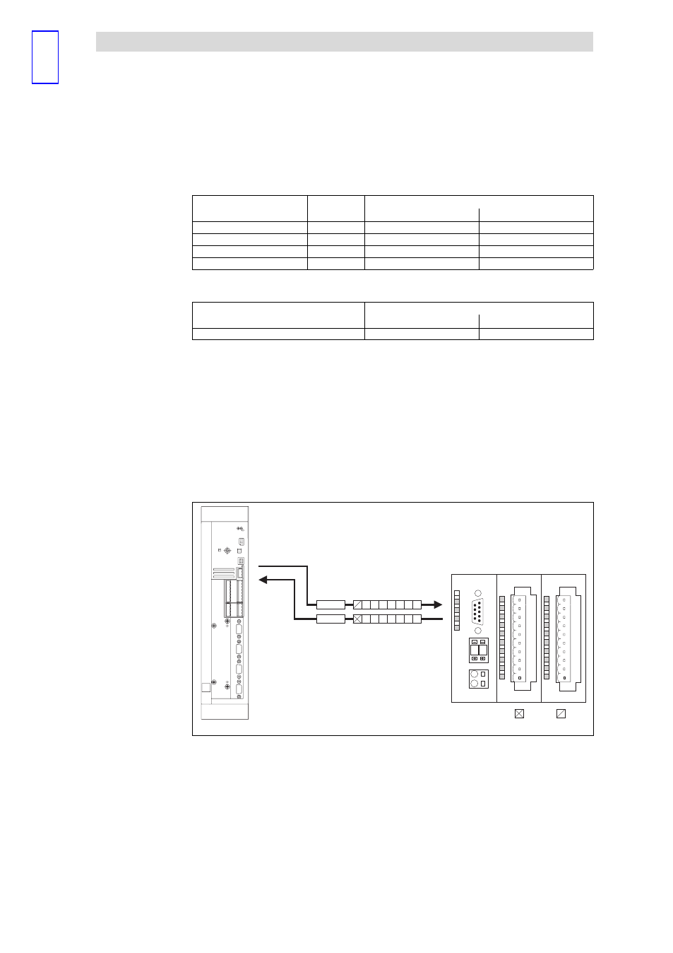
PDO1-Rx
CAN_OUT3
CAN_IN3
PDO1-Tx
0
1
epm−t112
Fig. 8.3−2
Data transmission between I/O system IP20 and controller
PDO−Rx
The I/O system IP20 receives the status information from the controller
PDO−Tx
The I/O system IP20 transmits the status information to the controller
0
Controller with node address 1 (C0350 = 1)
769
d
(basic identifier) + 1 (node address) = 770
d
(identifier)
768
d
(basic identifier) + 1 (node address) = 769
d
(identifier)
1
CAN gateway of the modular system (or a module of the compact system)
with node address 2
768
d
(basic identifier) + 2 (node address) = 770
d
(identifier)
767
d
(basic identifier) + 2 (node address) = 769
d
(identifier)
Solution