5 process image of the modular system, Process image of the modular system, Networking via system bus (can) – Lenze EPM−T9XX Modular system User Manual
Page 179
Transmitting process data
Process image of the modular system
Networking via system bus (CAN)
8.3
8.3.5
L
8.3−5
EDSPM−TXXX−9.0−11/2009
8.3.5
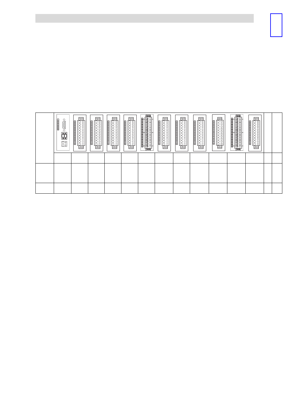
Process image of the modular system
The process image of the modular system is explained on the basis of the following
example. In addition to the CAN gateway, maximally 32 modules can be
connected.
Module
L
0
1
L
L
L
L
EPM – T211
L
L
L
L
EPM – T211
L
CAN
Gateway
8×DI
8×DI
8×DI
8×DI
16×DI
8×DO
4ЧAI
2/4Ч
Counter
SSI
interface
1×counter
/ 16×DI
4×AI/AO
—
—
Process
data
—
1 byte TX 1 byte TX 1 byte TX 1 byte TX
2 bytes
TX
1 byte RX
8 bytes
TX
10 bytes
TX
10 bytes
RX
4 bytes TX
4 bytes
RX
6 bytes TX
6 bytes
RX
4 bytes TX
4 bytes
RX
Module
No.
M0
M1
M2
M3
M4
M5
M6
M7
M8
M9
M10
M11
...
M32
This manual is related to the following products: