5 profibus-dp, 1 wiring, Profibus−dp – Lenze EPM−T9XX Modular system User Manual
Page 165: Wiring, Electrical installation, 5 profibus−dp, Profibus−dp wiring, 1200 m, Basic wiring of profibus 5
PROFIBUS−DP
Wiring
Electrical installation
7.5
7.5.1
L
7.5−1
EDSPM−TXXX−9.0−11/2009
7.5
PROFIBUS−DP
7.5.1
Wiring
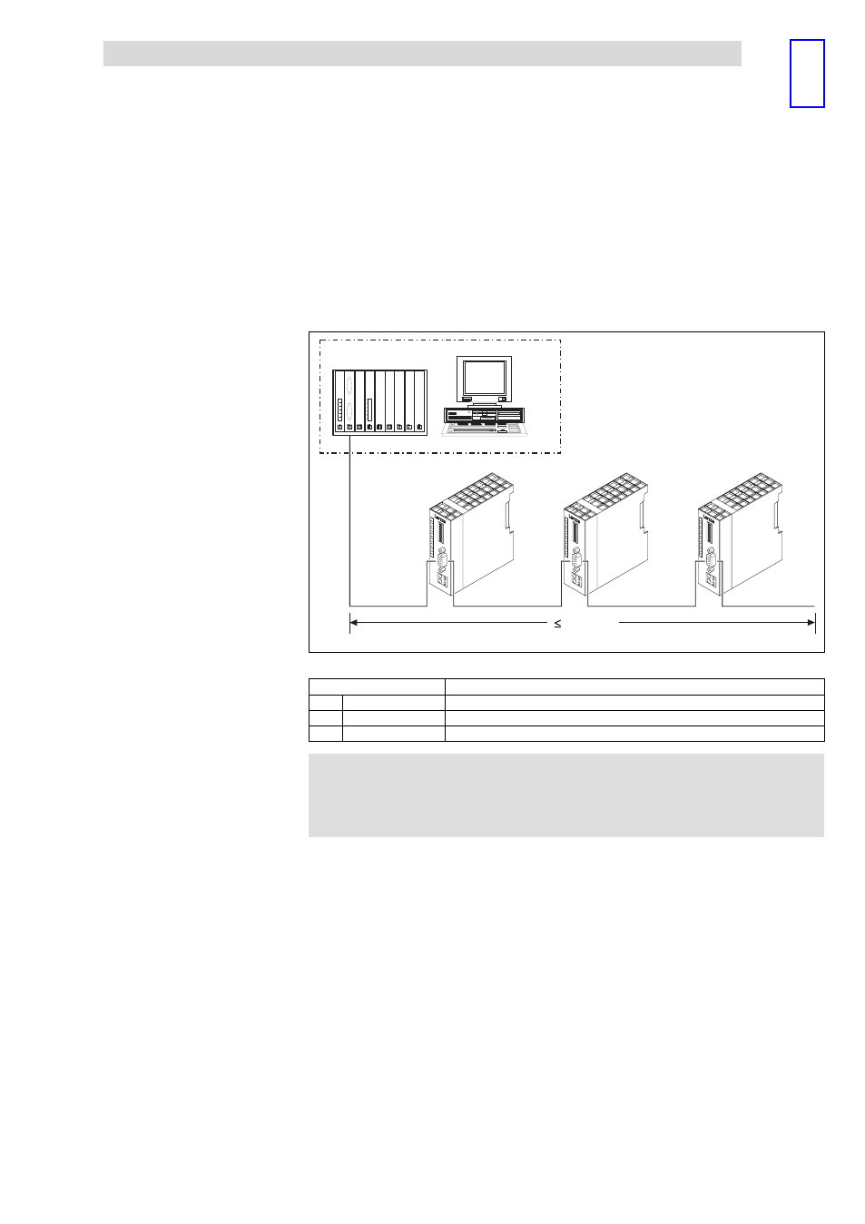
The design of the bus system PROFIBUS−DP is shown in the general drawing.
1
2
2
3
3
3
2
PW
ER
RD
DE
DC
24V
+
-
1
2
X1
EP
M
– T
12x
xx.x
x
ADR.
64
32
16
8
4
2
1
-
1
0
PW
ER
RD
DE
DC
24V
+
-
1
2
X1
EP
M
– T
12x
xx.x
x
ADR.
64
32
16
8
4
2
1
-
1
0
PW
ER
RD
DE
DC
24
V
+
-
1
2
X1
EP
M
– T
12x
xx.x
x
ADR.
64
32
16
8
4
2
1
-
1
0
1200 m
epm−t222
Fig. 7.5−1
PROFIBUS−DP with RS485 cabling (without repeater)
Element
Note
1
Master
Master computer, e.g. PC or PLC with PROFIBUS−DP master interface module
2
Bus cable
Adjust the baud rate to the length of the bus cable
3
Slave
PROFIBUS Gateway or PROFIBUS GatewayECO
)
Note!
When using a repeater, max. 125 devices can communicate via
the PROFIBUS.
Basic wiring of PROFIBUS
5
This manual is related to the following products: