2 prefixes and directions – Festo Электромотор MTR-DCI User Manual
Page 33
1. System overview
1-13
Festo P.BE-MTR-DCI-PB-EN en 1209a
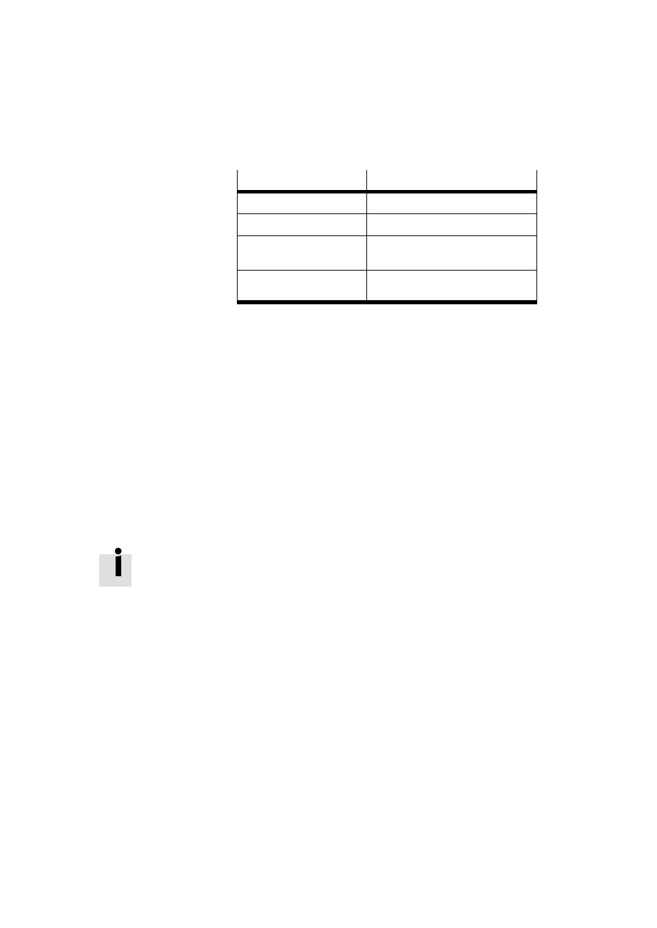
Point of reference
Calculation rule
Axis zero point
AZ
= REF
+ a
Project zero point
PZ
= AZ
+ d
= (REF
+ a) + d
Lower software end posi-
tion
LSE
= AZ
+ b
= (REF
+ a) + b
Upper software end posi-
tion
USE
= AZ
+ c
= (REF
+ a) + c
Tab. 1/2: Calculation rules for the measuring reference sys-
tem with incremental measuring systems
1.5.2
Prefixes and directions
All offsets and position values are vectors (with prefix). The
+/- active direction of the vectors can be assigned to the dir-
ection of rotation of the motor shaft (view on the motor
shaft). The factory setting for a clockwise direction of rotation
is “+”; for an anti-clockwise direction of rotation, “-”. The
assignment can be reversed on the control panel (see chapter
4.4) or via the FCT. This can be advantageous when using
right-angle or toothed belt gearboxes. A new reference travel
is required after a reversal of direction.
The direction in which the effective load moves is dependent
on the gear unit, the spindle type (clockwise/anti-clockwise
rotation), the prefix for the position specifications (+/-) and
the active direction set: