Festo Электромотор MTR-DCI User Manual
Page 153
5. Commissioning
5-65
Festo P.BE-MTR-DCI-PB-EN en 1209a
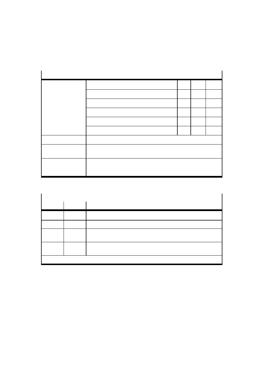
Overview of parameters involved (see also section B.1.12)
Parameters involved
Description
FCT
PNU
CI
Axis zero point offset
x
1010
607Ch
Homing method
x
1011
6098h
Homing speeds
x
1012
6099h
Homing required
–
1014
23F6h
Maximum homing torque
x
1015
23F7h
Start
CPOS.B2 = positive edge: Start homing
Feedback
SPOS.B1 = positive edge: Acknowledge start
SPOS.B7 = drive homed to reference point
Requirement
Device control by PLC/fieldbus
Controller must be in status “Operation enabled”
No active command for jogging
Tab. 5/18: Parameters involved in homing
Homing methods
1)
hex.
dec.
Description
17h
23
Search for reference switch in positive direction.
1Bh
27
Search for reference switch in negative direction.
EFh
-17
Search for negative stop. The point found is the reference position. As the
axis must not stand still at the stop, the axis zero point offset must be ≠ 0.
EEh
-18
Search for positive stop. The point found is the reference position. As the
axis must not stand still at the stop, the axis zero point offset must be ≠ 0.
1)
For detailed description of homing methods see section 5.2.2.
Tab. 5/19: Overview of homing methods