3 monitoring and recording triggered activity – Multichannel Systems MC_Rack Manual User Manual
Page 51
Step by Step Tutorial
45
3.3 Monitoring and Recording Triggered Activity
3.3.1 Triggering MC_Rack on the Stimulus
When recording evoked responses, such as in a LTP or PPF experiment, you usually want to
synchronize the data displays and the recording to the electrical stimulation. For this purpose,
you can feed in TTL pulses to the digital input bits of the digital input channel. In the standard
configuration, three BNC sockets are available for applying up to three separate trigger pulses.
You can upgrade the system with a digital IN / OUT expansion that supports all 16 digital input
(and output) bits that are provided by the MC_Card. For more information, see the ME- or MEA-
System manual.
Note: It is recommended to use the digital input port for feeding in TTL signals.
The analog inputs are intended for analog signals, like patch clamp data, for example.
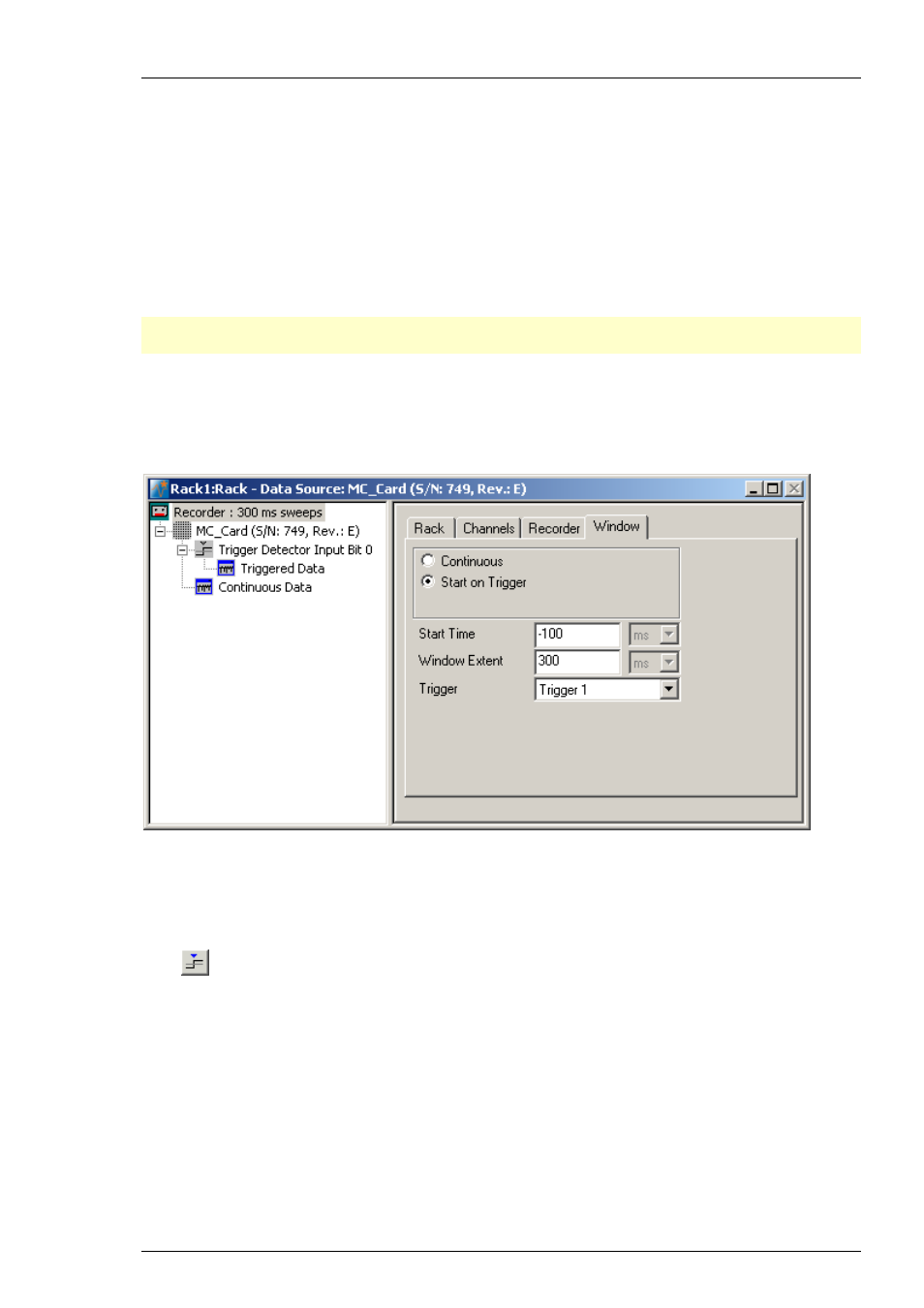
For triggering MC_Rack, we need to set up a Trigger Detector in the virtual rack. The trigger
stream generated by the Trigger Detector can then be used for triggering Data Displays,
Analyzers, and the Recorder.
See also the sample rack Display_Triggered.rck.
1. Configure your stimulator to output a TTL pulse that is synchronized to the stimulus pattern.
If you are using a Stimulus Generator (STG) from MCS, you can program a Sync Out channel.
2. Connect the TTL output to digital input bit 0 (the first BNC socket). If you are using a MEA-System,
make sure not to confuse the digital inputs with the analog inputs.
3. Click
on the MC_Rack toolbar to add a Trigger Detector to the virtual rack.
4. In the tree view pane of the virtual rack, select the Trigger Detector, and click the Trigger page.