Multichannel Systems MC_Rack Manual User Manual
Page 130
MC_Rack Manual
124
Setting up the Hardware
To generate real-time feedback stimulation to a biological sample, you need an advanced data
acquisition system (MEA2100-System, USB-MEA- / ME-System), and a stimulus generator STG.
The digital output channel of the data acquisition has 16 bits. Bit 0 is accessible directly via Lemo
connector. In MEA2100-Systems bit 0 to bit 3 are separately available via Lemo connectors, but
you do not need a cable connection, because of the internal 3-channel STG. If you work with more
that one bit in USB-MEA- / ME-Systems, you need the Digital In / Out Extension (Di/o). This device
gets connected to the Digital IN / OUT of the data acquisition and provides access to all 16 input
and 16 output bits via standard BNC connectors.
Each output bit of the digital channel can be connected to one or more Trigger IN connectors
of a STG. Please see the STG manual on how to start stimulation on the Trigger IN.
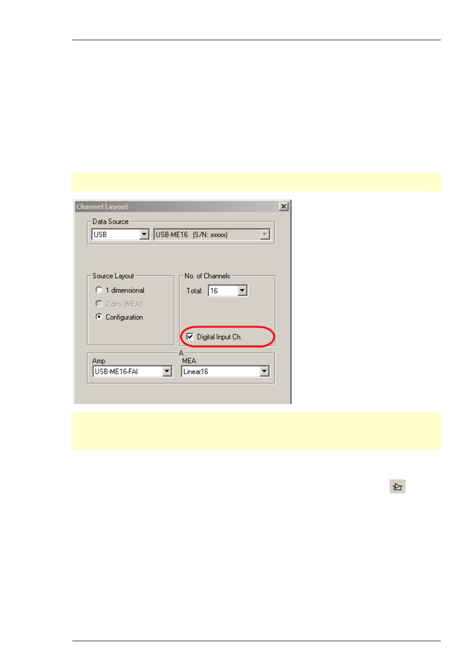
Important: It is a requirement to select the check box “Digital Input” in “Channel Layout”
of the “Data Source Setup”. Otherwise the real-time feedback feature is not available!
Important: The feedback signal from the processor module will be sent to digital outputs and
digital inputs as well. The DIG OUT is used for the connection to the STG. The respective DIG IN
channels can be used to monitor the generated feedback signals with a digital display in MC_Rack.
Therefore you can not apply external digital input signals to the DIG IN bits in use.
Setting up the Software
Click Edit menu and add “Real-time Feedback” or click the real-time feedback icon
in the
toolbar.
The real-time feedback tool automatically opens a display window, which will show the raw
data or data filtered by the digital hardware filter of the real-time feedback tool, the spike
detection level and the TTL feedback signal. The starting point of the trigger is marked by the
small red triangle above. The duration of the trigger is indicated. You can change the color of the
signal traces with a right click onto the trace as usual. Spike detection thresholds of individual
electrodes can be adjusted by moving them with the mouse in the display window. In the example
shown below, a 5 ms TTL is generated in response to every detected spike.