Multichannel Systems MC_Rack Manual User Manual
Page 43
Step by Step Tutorial
37
Defining the display layout
Note: You can set up any channel layout that meets your requirements and save it for later use.
You can pick preconfigured channel maps for all MEAs available from Multi Channel Systems
from the MCS Channel Maps drop down list.
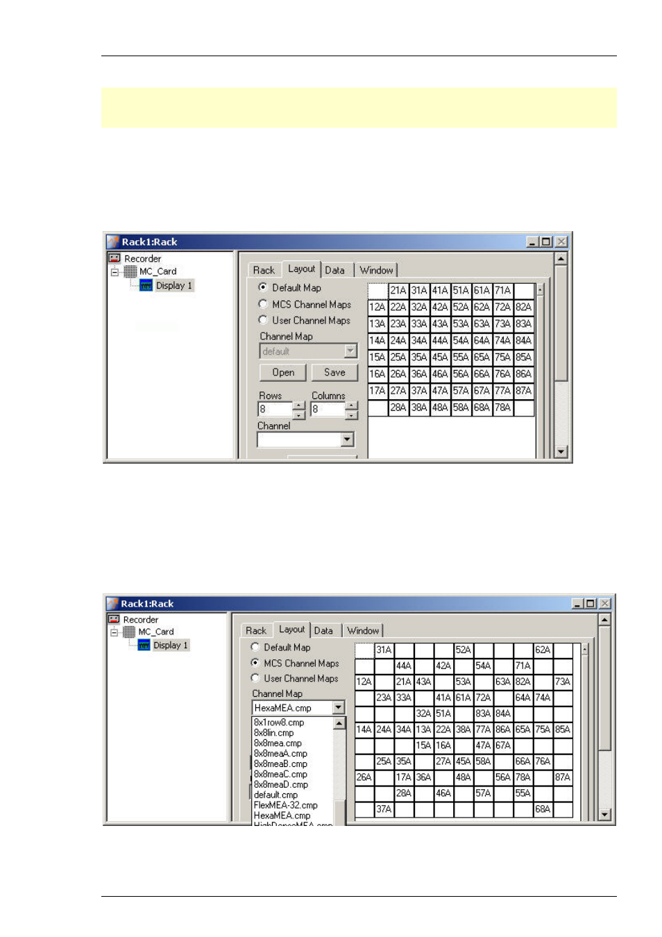
1. In the tree view pane of the virtual rack, select the Display 1 and click the Layout tab.
You see the currently used display layout of the Default Map: The standard 8x8 grid. The
electrodes are labeled in relationship to their position in the electrode grid, respectively to their
coordinates. The first number refers to the x-axis (column), the second number refers to the y-axis
(row). The character refers to the MEA, MEA A in this case, that is important when using more
than one MEA amplifier.
.
2. To load a different Channel Map, click MCS Channel Maps or if the channel map is user
defined, click User Channel Maps. You can use the Channel Map drop down menu or you
browse your folders and open the MC_Rack program folder. In the Channel Maps folder,
you will find a selection of standard layouts, for example, for different MEA types, layouts for
the MEA120-System (8x8meaA.cmp and 8x8meaB.cmp for the two separate MEA amplifiers), and
various other layouts for single electrode columns on a MEA, for example. Select an appropriate
channel map and click Open. The MEA layout appears on he right side of the dialog box and the
display shows the channels in the selected layout accordingly.
.
3. For setting up a custom layout, enter the desired number of rows and columns.
The layout grid displayed on the right is updated accordingly.