Multichannel Systems MC_Rack Manual User Manual
Page 40
MC_Rack Manual
34
3. Click
the
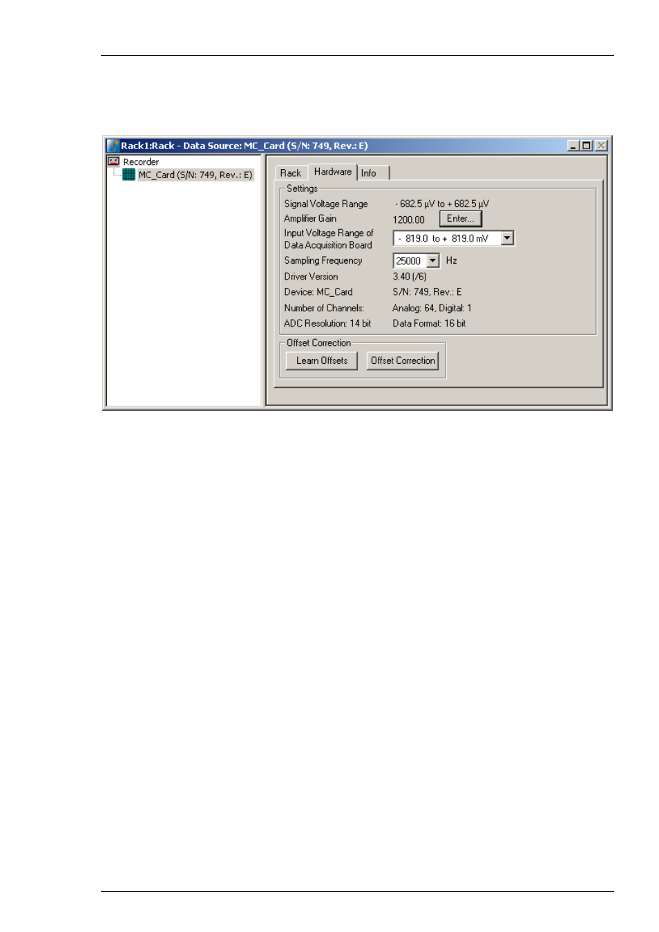
Hardware tab. Here, you can define hardware related parameters. Please note that the
amplifier gain is an intrinsic property of the amplifier and cannot be altered, whereas the input
voltage range and the sampling rate of the data acquisition card can be adjusted to your
needs. On this page, you will also find hardware related information like the MC_Card driver
version and the serial number. Please keep this information at hand when contacting the support.
4. Click
Enter to enter the Amplifier Gain settings according to your hardware. The gain settings
are used for scaling and displaying the signals properly. So if you specified a wrong gain, you
would perceive wrong signal amplitudes leading to false documentation and results. The default
settings are 1200 for the standard MEA1060 amplifier, and 1100 for the standard MEA1060-BC
amplifier. The amplifier gain of the MEA2100-System is automatically set, depending on the
version of the hardware. If you have a ME-System, you should enter the total gain of the
amplifiers. For example, if you have a MPA8I (with a gain of 10) and a filter amplifier with
a gain of 100, you have a total gain of 1000. Please check the technical specifications of the
connected amplifier(s) and make sure that you enter an appropriate value.
5. Select
an
Input Voltage Range of Data Acquisition Board for the MC_Card from the drop-
down list. For standard signals and a standard gain amplifier, the default input range of -819
to +819 will be fine. You need a higher input voltage range if your biological sample generates
higher voltages, for example, cardiac signals from whole-heart preparations, and/or the amplifier
gain is considerably higher. The lower the input voltage range, the higher is the voltage
resolution. Please see also Defining MC_Card Settings in the MC_Rack Features section.
6. The
Signal Voltage Range is calculated from the Input Voltage Range of the Data Acquisition
Board divided through the Amplifier Gain Factor.
7. Select
a
Sampling Rate from the drop down list. For most applications, 25 kHz will be fine.
Please see also Defining MC_Card Settings in the MC_Rack Features section.
8. An
Offset Correction is generally not necessary. You may use it when you observe a disturbing
voltage offset on the input channels. Or you may use it during testing the system with a test
model probe. Make sure that there are no signals on the channels when using the offset
correction. Click Offset Correction to activate the Offset Correction. Click Learn Offsets to
perform an individual offset correction for each input channel. MC_Rack takes 100 ms of the
recorded data in the moment when the button is pressed to calculate the DC offset. The mean of
this 100 ms sweep is subtracted from the recorded data as long as the Offset Correction button
is pressed. The individual offset values for each channel are saved in the local settings of the data
acquisition computer and are only overwritten when you click Learn Offsets again. Make sure
you press the Learn Offsets button only when you have no real input signals or irregular noise
signals on the electrodes. To be on the safe side, connect a test model probe to the amplifier.