Multichannel Systems MC_Rack Manual User Manual
Page 162
MC_Rack Manual
156
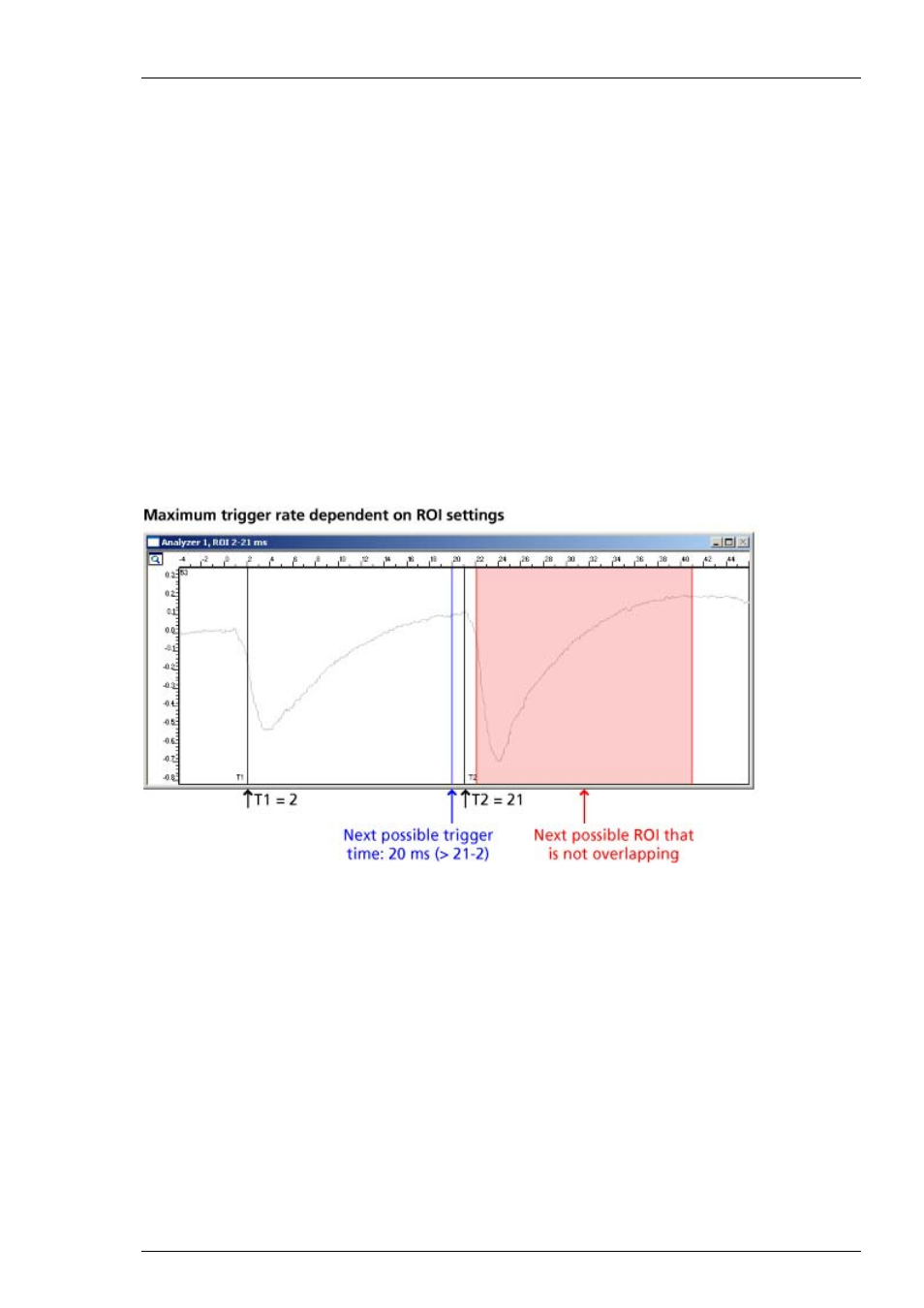
Maximum trigger rate
Please note that the ROI must be defined in a way that the trigger rate does not cause ROIs
to overlap.
The maximum refresh rate of the Analyzer display is determined by the x axis range selected
from the drop-down list on the display toolbar. In contrast, the Analyzer functionality, that is,
the parameter extraction, is directly related to the trigger events, not to the display. The
Analyzer does not allow overlapping regions of interest, that is, trigger events that would lead
to overlapping ROIs will be ignored. In other words, the Analyzer will only accept following
trigger events after time point T2 minus T1. (For example, for T1 = 2 ms and T2 = 21 ms, new
trigger inputs will be accepted only at 20 ms or later after the first trigger event, because 20 ms
plus 2 ms will result in the new T1 = 22 ms, and that is after the end of the first ROI = 21 ms.)
To avoid misunderstandings, it is recommended that the refresh rate of the display corresponds
to the expected maximum trigger event rate, by either adjusting the refresh rate of the
Analyzer, or by adjusting the dead time in the Trigger Detector. (If the trigger event rate is
lower than the display refresh rate, the display will be refreshed only at a new trigger event.)
Example: If you have trigger events at a 10 Hz rate, that is, at a 100 ms trigger interval, but the
display refresh rate is set to 200 ms or +/-100 ms, the Analyzer display will miss every second
sweep, but the selected parameter, for instance the peak-peak amplitude, will be extracted from
each sweep, that is, each 100 ms (provided the ROI and trigger settings do not lead to overlapping
ROIs).
Defining the Bin Size (Continuous Mode)
If you have a continuous data stream, you can define the time intervals from which the analyzer
will extract the selected parameter. For example, if you choose intervals of 1 s, the parameter,
for example the spike rate, is measured for 1 s intervals. For example, the spike number may
be 80 in the first second, 30 in the second second, and 40 in the third second, and so on.
The appropriate bin size depends on the expected signal rate, and on the purpose of the
Analyzer.
For example, when monitoring the cardiac signal rate of a cardiomyocyte preparation, it does not
make sense to use a 1 s bin size, because the expected signal rate is in the range of 1 Hz, that is,
either there is a signal detected in the bin or not. This would result in an extracted rate switching
between 0.00 and 1.00 Hz. For this purpose, you would need a higher bin size, for example, 5 s.
Please note that a higher bin size affects your resolution on the other hand. That is, with a bin
size of 5 s, the rate will be updated only every 5 s.