Xl™ series – Xylem XL Series H-522 - Plus User Manual
Page 98
11-4 Analog Inputs / 5 Volt Excitation
XL™ Series
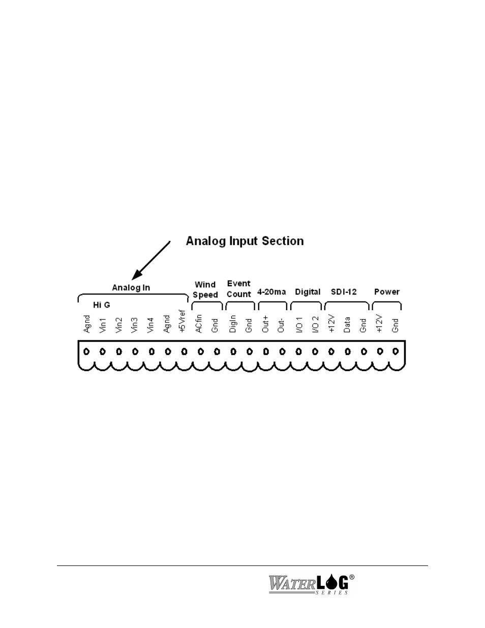
Figure 11-1 Analog Input Section
Even though when in the differential mode the value returned is not referenced to ground, the
voltages on channel 1 and 2 must be between 0.0 volts and 5.0 volts with respect to ground. A
voltage on channel 1 of 7.0 volts and a voltage on channel 2 of 4.0 volts both with respect to
ground would not work because channel one is greater than 5.0 volts even though the difference
is only 3.0 volts. A voltage on channel 1of 4.5 volts and a voltage on channel 2 of 2.5 volts both
with respect to ground would be ok since both channels are in range and the returned value
would be 2.0 volts, 4.5-2.5=2.0.
11.4 Analog Input Connections
The first seven connections on the twenty pin terminal block are used for analog input functions.
This includes four analog inputs, two analog grounds and one +5.00 volt excitation connection.
11.4.1 Analog Inputs and Analog Grounds Connections
The four analog input channels are labeled Vin1 to Vin4. There are two analog ground
connections. In order to preserve signal integrity, it is important to use the analog grounds
only for sensors connected to the analog section of the XL™. The current flowing through an
analog sensor is relatively small and normally very stable. This provides stable voltages produced
by these sensors. If a digital sensor has its ground connection tied into the analog ground, the
currents from the digital sensor will flow through the analog circuitry causing voltage level shifts
and noise based on digital switching. There should be sufficient digital ground connection points
for the digital sensors.