Xl™ series – Xylem XL Series H-522 - Plus User Manual
Page 23
XL™ Series
Hardware Options and Installation 2-9
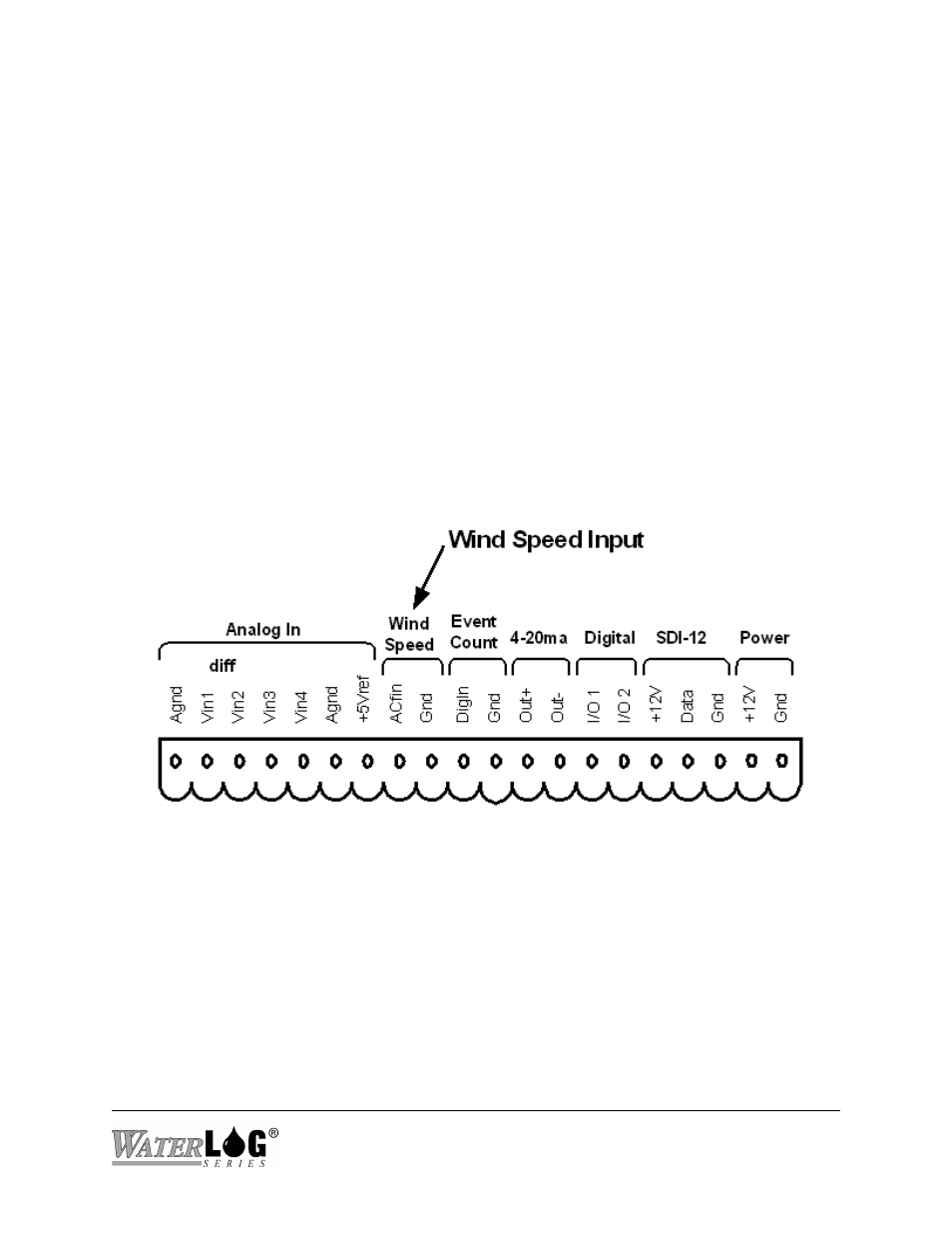
Figure 2-7 Wind Speed Input
2.2.8.3 Switched +5.00 Volt Reference Excitation
The +5.00 Volt reference output is used for analog sensors requiring a precision reference
voltage. The output current source maximum level is 10 milliamps. Exceeding this limit will
cause the excitation to possibly sag, and result in possible data errors. The Analog to Digital
converter uses this excitation for its reference to provide a ratio-metric relationship for sensors
using the excitation. What this means is that if a sensor causes loading to the excitation and drags
it down to 4.75 volts for example, then the A/D converter will use the 4.75 volts as its reference,
and maintain a full scale input equal to the reduced excitation. To a point this will reduce errors
in data when the excitation is used. If the excitation is being loaded down and some analog input
channels are not using the excitation, but produce a voltage output on there own, then these
inputs will have a much greater error.
2.2.9 Wind Speed Input (AC Frequency Input)
Pins 8 and 9 of the terminal block provide connection points for a low-level AC signal. Several
wind speed sensors produce a low level AC sine wave directly compatible to this input.
The wind speed input is a frequency counter capable of accepting low-level signals in the range
of ±0.075 volts and greater, however, this input should not be exposed to signals greater than
approximately ±5.0 volts. The input signal must be bipolar, that is, the input signal must vary
above and below the reference point or ground. Several wind speed sensors use a simple,
propeller driven generator that produces an AC signal suitable for this input.