Rainbow Electronics DS31256 User Manual
Page 71
DS31256
71 of 181
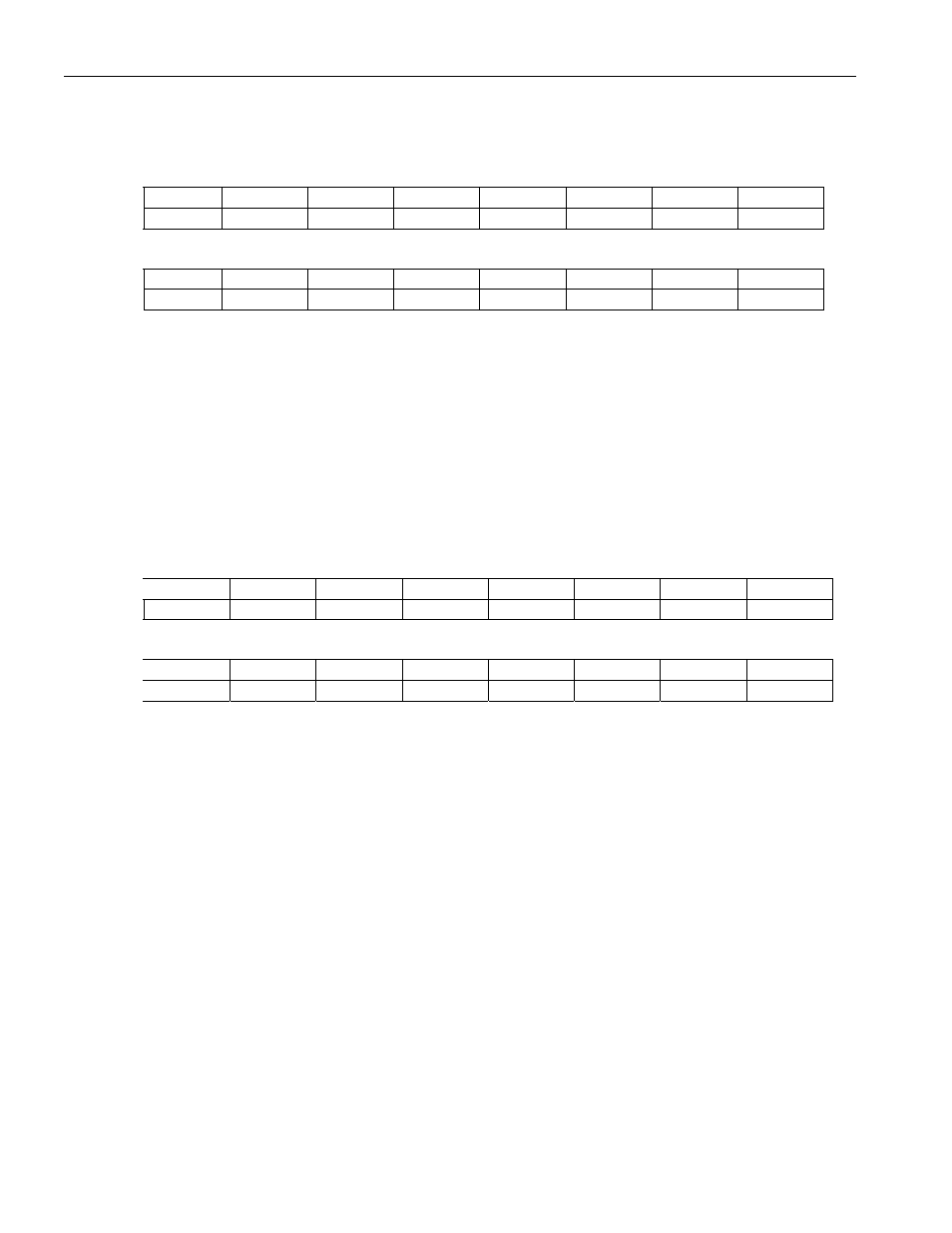
Register Name:
RHPL
Register Description: Receive HDLC Maximum Packet Length
Register Address:
0410h
Bit
# 7 6 5 4 3 2 1 0
Name RHPL7 RHPL6 RHPL5 RHPL4 RHPL3 RHPL2 RHPL1 RHPL0
Default
0 0 0 0 0 0 0 0
Bit
# 15 14 13 12 11 10 9 8
Name
RHPL15 RHPL14 RHPL13 RHPL12 RHPL11 RHPL10 RHPL9 RHPL8
Default
0 0 0 0 0 0 0 0
Note: Bits that are underlined are read-only; all other bits are read-write. This is a globe control; only one per device, not one for each
individual HDLC channel.
Bits 0 to 15/Receive HDLC Packet Length (RHPL0 to RHPL15). If the receive length-detection enable bit is
set to 1, the HDLC engine checks the number of received octets in a packet to see if they exceed the count in this
register. If the length is exceeded, the packet is aborted and the remainder is discarded. The definition of “octet
length” is everything between the opening and closing flags, which includes the address field, control field,
information field, and FCS.
Register Name:
THCDIS
Register Description: Transmit HDLC Channel Definition Indirect Select
Register Address:
0480h
Bit
# 7 6 5 4 3 2 1 0
Name HCID7 HCID6 HCID5 HCID4 HCID3 HCID2 HCID1 HCID0
Default 0 0
0
0
0
0
0
0
Bit
# 15 14 13 12 11 10 9 8
Name IAB
IARW
n/a n/a n/a n/a n/a n/a
Default 0
0
0
0
0
0
0
0
Note: Bits that are underlined are read-only; all other bits are read-write.
Bits 0 to 7/HDLC Channel ID (HCID0 to HCID7)
00000000 (00h) = HDLC channel number 1 (also used for the fast HDLC engine on port 0)
00000001 (01h) = HDLC channel number 2 (also used for the fast HDLC engine on port 1)
00000010 (02h) = HDLC channel number 3 (also used for the fast HDLC engine on port 2)
00000011 (03h) = HDLC channel number 4
11111111 (FFh) = HDLC channel number 256
Bit 14/Indirect Access Read/Write (IARW). When the host wishes to read data from the internal transmit HDLC
definition RAM, this bit should be written to 1 by the host. This causes the device to begin obtaining the data from
the channel location indicated by the HCID bits. During the read access, the IAB bit is set to 1. Once the data is
ready to be read from the THCD register, the IAB bit is set to 0. When the host wishes to write data to the internal
transmit HDLC definition RAM, this bit should be written to 0 by the host. This causes the device to take the data
that is currently present in the THCD register and write it to the channel location indicated by the HCID bits.
When the device completes the write, the IAB is set to 0.
Bit 15/Indirect Access Busy (IAB). When an indirect read or write access is in progress, this read-only bit is set
to 1. During a read operation, this bit is set to 1 until the data is ready to be read. It is set to 0 when the data is
ready to be read. During a write operation, this bit is set to 1 while the write is taking place. It is to 0 once the
write operation is complete.