Rainbow Electronics DS31256 User Manual
Page 64
DS31256
64 of 181
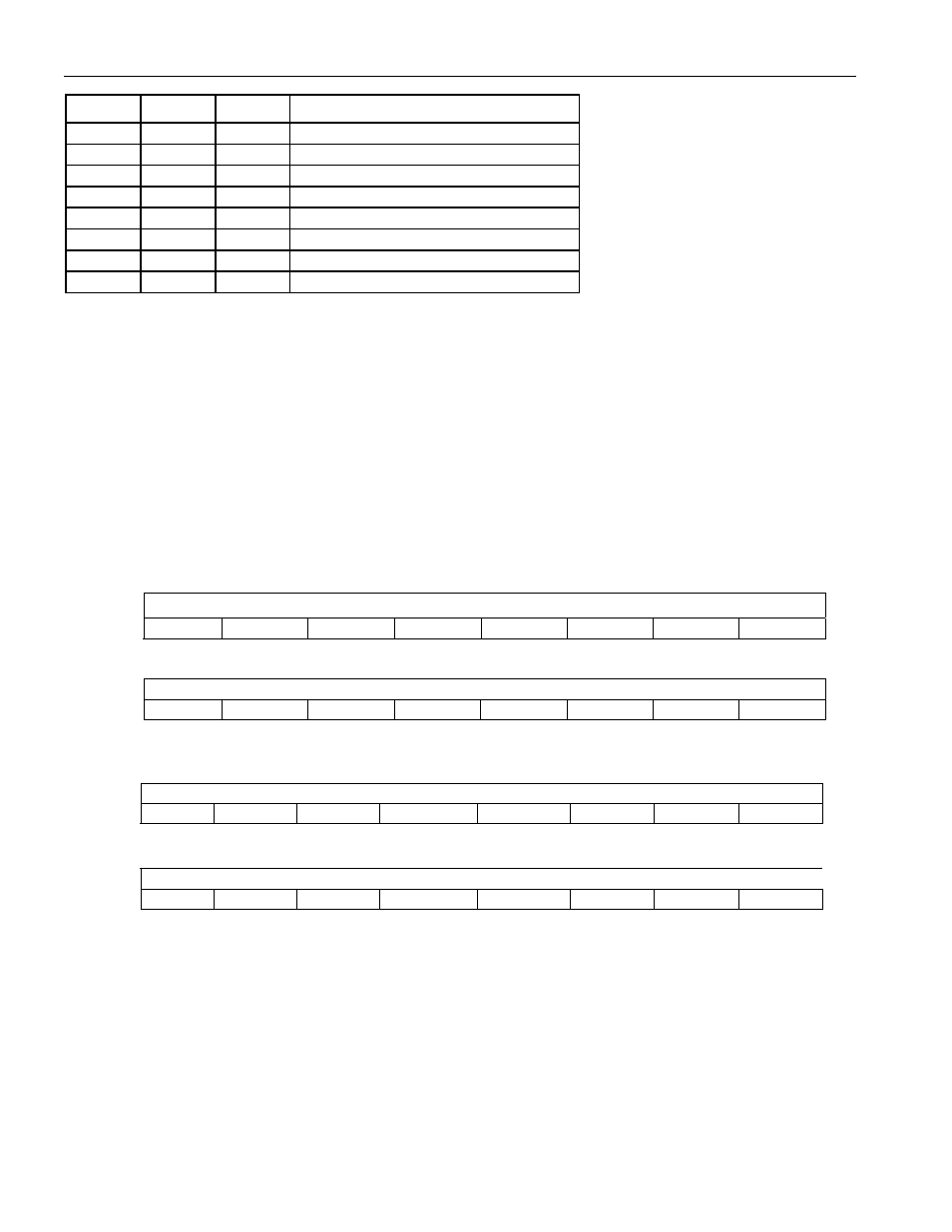
EIB2 EIB1 EIB0
Error
Rate
Inserted
0 0 0
No
errors
automatically
inserted
0 0 1
10E-1
0 1 0
10E-2
0 1 1
10E-3
1 0 0
10E-4
1 0 1
10E-5
1 1 0
10E-6
1 1 1
10E-7
Bits 8 to 15/Alternating Word Count Rate. When the BERT is programmed in the alternating word mode, the
words repeat for the count loaded into this register, then flip to the other word and again repeat for the number of
times loaded into this register. The valid count range is from 05h to FFh.
Register Name:
BERTBRP0
Register Description: BERT Repetitive Pattern Set 0
Register Address:
0508h
Register Name:
BERTBRP1
Register Description: BERT Repetitive Pattern Set 1
Register Address:
050Ch
BERTRP0: BERT Repetitive Pattern Set 0 (lower word)
Bit
# 7 6 5 4 3 2 1 0
Name
BERT Repetitive Pattern Set (lower byte)
Default
0 0 0 0 0 0 0 0
Bit
# 15 14 13 12 11 10 9 8
Name
Bert Repetitive Pattern Set
Default
0 0 0 0 0 0 0 0
BERTRP1: BERT Repetitive Pattern Set 1 (upper word)
Bit
# 23 22 21 20 19 18 17 16
Name
BERT Repetitive Pattern Set
Default
0 0 0 0 0 0 0 0
Bit #
31 30 29 28 27 26 25 24
Name
Bert Repetitive Pattern Set (upper byte)
Default
0 0 0 0 0 0 0 0
Note: Bits that are underlined are read-only; all other bits are read-write.
Bits 0 to 31/BERT Repetitive Pattern Set (BERTRP0 and BERTRP1). These registers must be properly loaded
for the BERT to properly generate and synchronize to either a repetitive pattern, a pseudorandom pattern, or an
alternating word pattern. For a repetitive pattern that is less than 32 bits, the pattern should be repeated so that all
32 bits are used to describe the pattern. For example, if the pattern was the repeating 5-bit pattern …01101…
(where the right-most bit is sent first and received first), then PBRP0 should be loaded with xB5AD and PBRP1
should be loaded with x5AD6. For a pseudorandom pattern, both registers should be loaded with all ones (i.e.,
xFFFF). For an alternating word pattern, one word should be placed into PBRP0 and the other word should be
placed into PBRP1. For example, if the DDS stress pattern “7E” is to be described, the user would place x0000 in
PBRP0 and x7E7E in PBRP1 and the alternating word counter would be set to 50 (decimal) to allow 100 Bytes of
00h followed by 100 Bytes of 7Eh to be sent and received.