Rainbow Electronics DS31256 User Manual
Page 104
DS31256
104 of 181
- FOR DMA USE ONLY/HOST CAN ONLY READ THIS FIELD -
dword 2; Bits 16 to 28/Byte Count. The DMA uses these 13 bits to keep track of the number of bytes stored in
the data buffer. Maximum is 8188 Bytes (0000h = 0 Bytes / 1FFCh = 8188 Bytes).
- FOR DMA USE ONLY/HOST CAN ONLY READ THIS FIELD -
dword 2; Bits 29 to 31/Threshold Count. These bits keep track of the number of data buffers that have been
filled so that the receive DMA knows when, based on the host-controlled threshold, to write to the done queue.
000 = threshold count is 0 data buffers
001 = threshold count is 1 data buffer
010 = threshold count is 2 data buffers
011 = threshold count is 3 data buffers
100 = threshold count is 4 data buffers
101 = threshold count is 5 data buffers
110 = threshold count is 6 data buffers
111 = threshold count is 7 data buffers
Register Name:
RDMACIS
Register Description: Receive DMA Channel Configuration Indirect Select
Register Address:
0770h
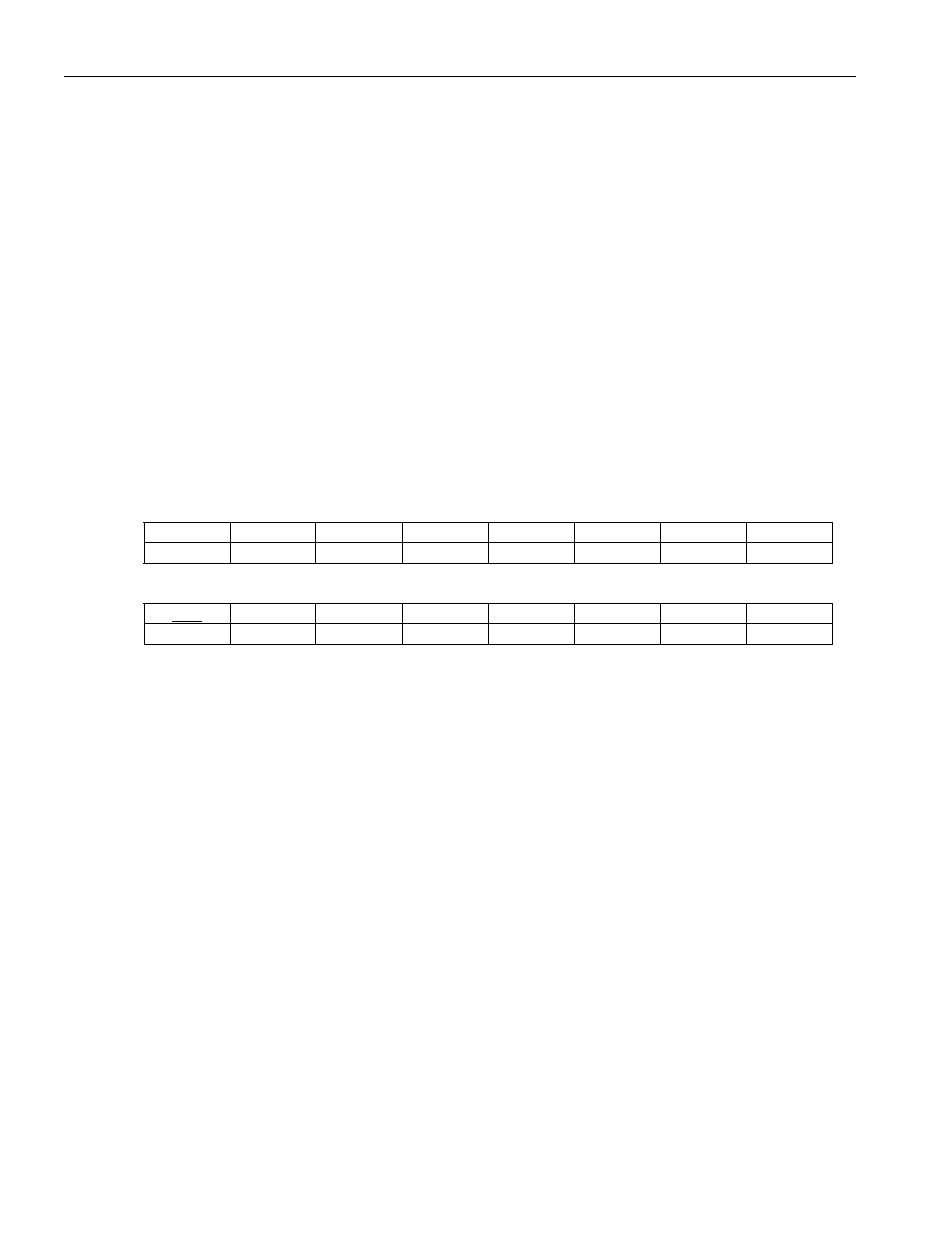
Bit
# 7 6 5 4 3 2 1 0
Name HCID7
HCID6
HCID5 HCID4 HCID3 HCID2 HCID1 HCID0
Default
0 0 0 0 0 0 0 0
Bit
# 15 14 13 12 11 10 9 8
Name IAB IARW n/a
n/a
n/a
RDCW2 RDCW1 RDCW0
Default
0 0 0 0 0 0 0 0
Note: Bits that are underlined are read-only; all other bits are read-write.
Bits 0 to 7/HDLC Channel ID (HCID0 to HCID7)
00000000 (00h) = HDLC channel number 1
11111111 (FFh) = HDLC channel number 256
Bits 8 to 10/Receive DMA Configuration RAM Word Select Bits 0 to 2 (RDCW0 to RDCW2)
000 = lower word of dword 0
001 = upper word of dword 0
010 = lower word of dword 1
011 = upper word of dword 1
100 = lower word of dword 2 (only word that the host can write to)
101 = upper word of dword 2
110 = illegal state
111 = illegal state
Bit 14/Indirect Access Read/Write (IARW). When the host wishes to read data from the internal receive DMA
configuration RAM, this bit should be written to 1 by the host. This causes the device to begin obtaining the data
from the channel location indicated by the HCID bits. During the read access, the IAB bit is set to 1. Once the data
is ready to be read from the RDMAC register, the IAB bit is set to 0. When the host wishes to write data to the
internal receive DMA configuration RAM, this bit should be written to 0 by the host. This causes the device to
take the data that is currently present in the RDMAC register and write it to the channel location indicated by the
HCID bits. When the device has completed the write, the IAB bit is set to 0.
Bit 15/Indirect Access Busy (IAB). When an indirect read or write access is in progress, this read-only bit is set
to 1. During a read operation, this bit is set to 1 until the data is ready to be read. It is set to 0 when the data is