Pci bridge mode, Figure 11-3. configuration mode, Figure 11-3 – Rainbow Electronics DS31256 User Manual
Page 149: 1 pci bridge mode
DS31256
149 of 181
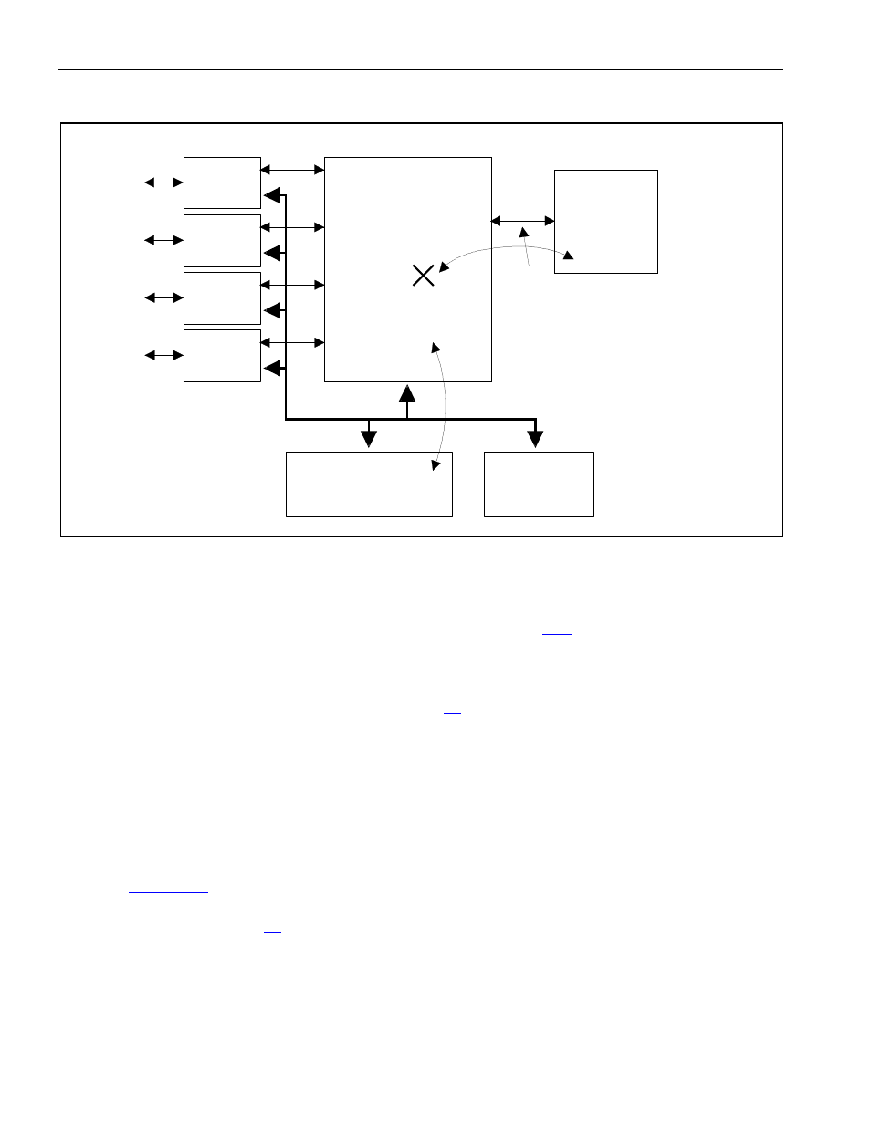
Figure 11-3. Configuration Mode
11.1.1 PCI
Bridge
Mode
In PCI bridge mode, data from the PCI bus can be transferred to the local bus. The local bus acts as a
“master” and creates all the necessary signals to control the bus. The user must configure the local bus
bridge mode control register (LBBMC), which is described in Section
With 20 address lines, the local bus can address 1MB address space. The host on the PCI bus determines
where to map this 1MB address space within the 32-bit address space of the PCI bus by configuring the
base address in the PCI configuration registers (Section
Bridge Mode 8-Bit and 16-Bit Access
During a bus access by the host, the local bus can determine how to map the four possible byte positions
from/to the PCI bus to/from the local bus data bus (LD) pins by examining the PCBE signals and the
local bus width (LBW) control bit that resides in the local bus bridge mode control (LBBMC) register. If
the local bus is used as an 8-bit bus (LBW = 1), then the host must only assert one of the PCBE signals.
The PCI data is mapped to/from the LD[7:0] signal lines; the LD[15:0] signal lines remain inactive. The
local bus block drives the A0 and A1 address lines according to the assertion of the PCBE signals by the
host. See
for details. If the host asserts more than one of the PCBE signals when the local
bus is configured as an 8-bit bus, then the local bus rejects the access and the PCI block returns a target
abort to the host. See Section
for details about a target abort.
T1 / E1
Framer or
Transceiver
Local Bus
DS31256 ENVOY
Host
Processor
and Main
Memory
PCI /
Custom
Bus
CPU Configures and
Monitors DS3134
Local RAM &
ROM
No
Access
Allowed
Only Used to
Transfer HDLC
Data
T1 / E1
Framer or
Transceiver
T1 / E1
Framer or
Transceiver
T1 / E1
Framer or
Transceiver