Rainbow Electronics DS31256 User Manual
Page 52
DS31256
52 of 181
Register Name:
CP[n]RDIS, where n = 0 to 15 for each port
Register Description: Channelized Port [n] Register Data Indirect Select
Register Address:
See the Register Map in Section
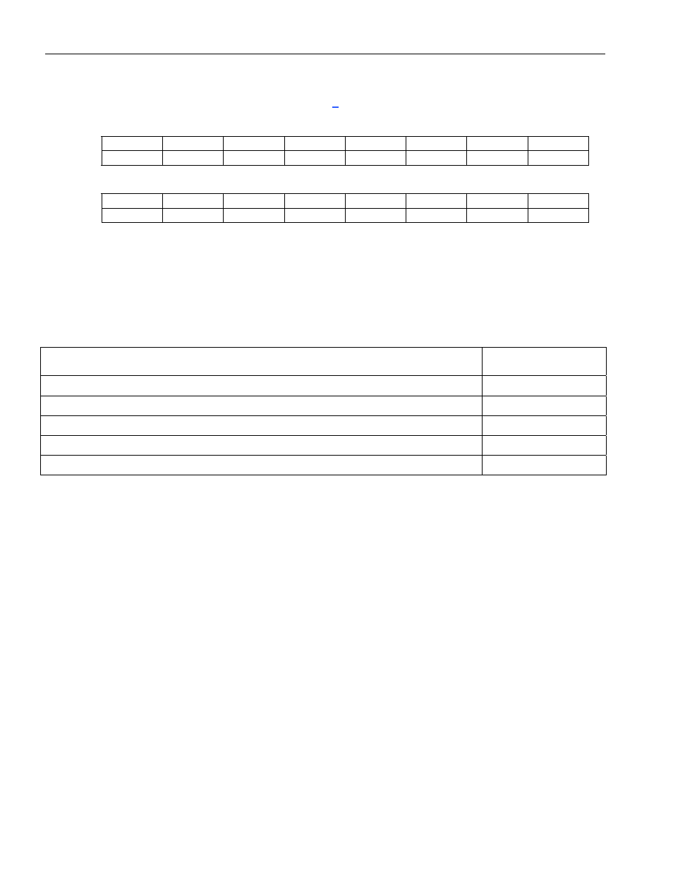
Bit
# 7 6 5 4 3 2 1 0
Name
n/a CHID6 CHID5 CHID4 CHID3 CHID2 CHID1 CHID0
Default 0 0
0
0
0
0
0
0
Bit
# 15 14 13 12 11 10 9 8
Name IAB
IARW
n/a n/a n/a n/a
CPRS1
CPRS0
Default 0
0
0
0
0
0
0
0
Note: Bits that are underlined are read-only; all other bits are read-write.
Bits 0 to 6/DS0 Channel ID (CHID0 to CHID6). The number of DS0 channels used depends on whether the port
has been configured for an unchannelized application or for a channelized application. If set for a channelized
application, the number of DS0 channels depends on whether the port has been configured in the T1, E1,
4.096MHz, or 8.192MHz mode.
0000000 (00h) = DS0 channel number 0
1111111 (7Fh) = DS0 channel number 127
PORT MODE
DS0 CHANNELS
AVAILABLE
Unchannelized (RUEN/TUEN = 1)
0
Channelized T1 (RUEN/TUEN = 0 and RSS0/TSS0 = 0 and RSS1/TSS1 = 0)
0 to 23
Channelized E1 (RUEN/TUEN = 0 and RSS0/TSS0 = 1 and RSS1/TSS1 = 0)
0 to 31
Channelized 4.096MHz (RUEN/TUEN = 0 and RSS0/TSS0 = 0 and RSS1/TSS1 = 1)
0 to 63
Channelized 8.192MHz (RUEN/TUEN = 0 and RSS0/TSS0 = 1 and RSS1/TSS1 = 1)
0 to 127
Bit 8/Channelized PORT RAM Select Bit 0 (CPRS0); Bit 9/Channelized PORT RAM Select Bit 1 (CPRS1)
00 = channelized DS0 data (C[n]DAT[j])
01 = receive configuration (R[n]CFG[j])
10 = transmit configuration (T[n]CFG[j])
11 = illegal selection
Bit 14/Indirect Access Read/Write (IARW). When the host wishes to read data from the internal channelized
PORT RAM, this bit should be written to 1 by the host. This causes the device to begin obtaining data from the
DS0 channel location indicated by the CHID bits and the data from the PORT RAM indicated by the CPRS0 and
CPRS1 bits. During the read access, the IAB bit is set to 1. Once the data is ready to be read from the CP[n]RD
register, the IAB bit is set to 0. When the host wishes to write data to the internal channelized PORT RAM, the
host should write this bit to 0. This causes the device to take the data that is currently present in the CP[n]RD
register and write it to the PORT RAM and the DS0 channel. When the device has completed the write, the IAB is
set to 0.
Bit 15/Indirect Access Busy (IAB). When an indirect read or write access is in progress, this read-only bit is set
to 1. During a read operation, this bit is set to 1 until data is ready to be read. It is set to 0 when the data is ready to
be read. During a write operation, this bit is set to 1 while the write is taking place. It is set to 0 once the write
operation has completed.