Layer 1 configuration register description, Ayer, Onfiguration – Rainbow Electronics DS31256 User Manual
Page 51: Egister, Escription, Figure 6-3. layer 1 register set, 3 layer 1 configuration register description
DS31256
51 of 181
Bit 14/Interrupt Enable for TCOFA (IETC)
0 = interrupt masked
1 = interrupt enabled
Bit 15/COFA Status Bit (TCOFA). This latched read-only status bit is set if a COFA is detected. A COFA is
detected by sensing that a sync pulse has occurred during a clock period that was not the first bit of the
193/256/512/1024-bit frame. This bit is reset when read and is not set again until another COFA has occurred.
6.3 Layer 1 Configuration Register Description
There are three configuration registers for each DS0 channel on each port (
, each of the 16 ports contains a PORT RAM, which controls the Layer 1 state machine. These
384 registers (three registers x 128 DS0 channels per port) comprise the PORT RAM for each port,
controlling and providing access to the Layer 1 state machine. The registers are accessed indirectly
through the channelized port register data (CP[n]RD) register. The host must first write to the
channelized port register data-indirect select (CP[n]RDIS) register to choose which DS0 channel and
channelized PORT RAM it wishes to configure or read. On power-up, the host must write to all the used
R[n]CFG[j] and T[n]CFG[j] locations to make sure they are set into a known state.
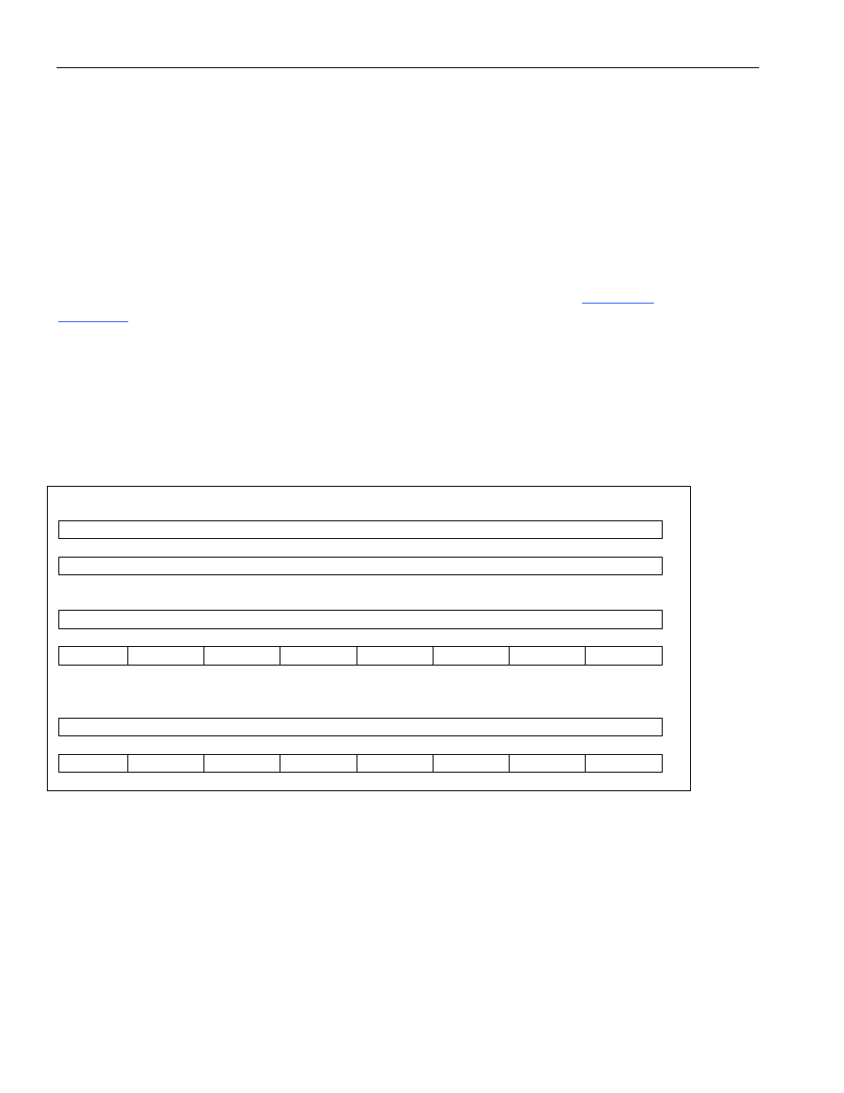
Figure 6-3. Layer 1 Register Set
C[n]DAT[j]: Channelized DS0 Data
LSB
RDATA(8): Receive DS0 Data
MSB
TDATA(8): Transmit DS0 Data
R[n]CFG[j]: Receive Configuration
LSB
RCH#(8): Receive HDLC Channel Number
MSB
RCHEN RBERT
n/a
RV54
n/a
CLLB
n/a
R56
T[n]CFG[j]: Transmit Configuration
LSB
TCH#(8): Transmit HDLC Channel Number
MSB
TCHEN TBERT
n/a
n/a
CNLB
n/a
TFAO
T56