Figure8.5 table indirect addressing, 3 defining a table, Defining a table – Avago Technologies LSI53C1010 User Manual
Page 196: Table indirect addressing
8-10
Writing Device Drivers with SCRIPTS
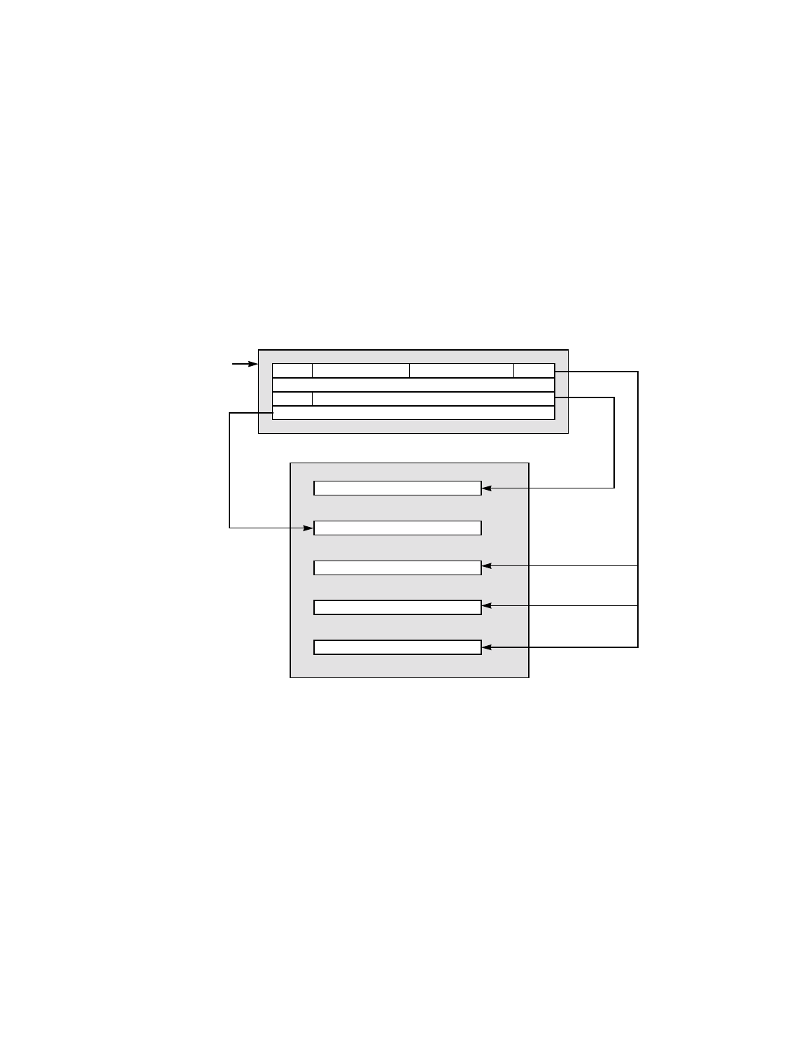
Enable Wide SCSI, Enable Ultra SCSI, and Clock Conversion Factor.
The Encoded SCSI destination ID in byte lane 2 is mapped into the SDID
register (0x06), and the period and offset information in byte lane 1 is
mapped into the SXFER register (0x05). The data must begin on a
4-byte boundary and must be located at the 24-bit signed offset from the
address contained in the DSA register.
shows these
relationships.
Figure 8.5
Table Indirect Addressing
8.6.3 Defining a Table
The first step in defining a table is to describe it in SCRIPTS code in
terms of the order and size of table entries, or buffers. An example is
shown in
Host Memory (table_0)
config
ID
period & offset
0
0
0
cmd_byte_count
command_address
DBC Register
DSPS Register
SCNTL3 Register
SDID Register
SXFER Register
SCSI Device
DSA
(DSA + command_offset:)
Select/Reselect
Block Move