Figure3.29 read/write instruction example, 5 block move instruction example, Block move instruction example – Avago Technologies LSI53C1010 User Manual
Page 118: Read/write instruction example
3-78
The SCSI SCRIPTS Processor Instruction Set
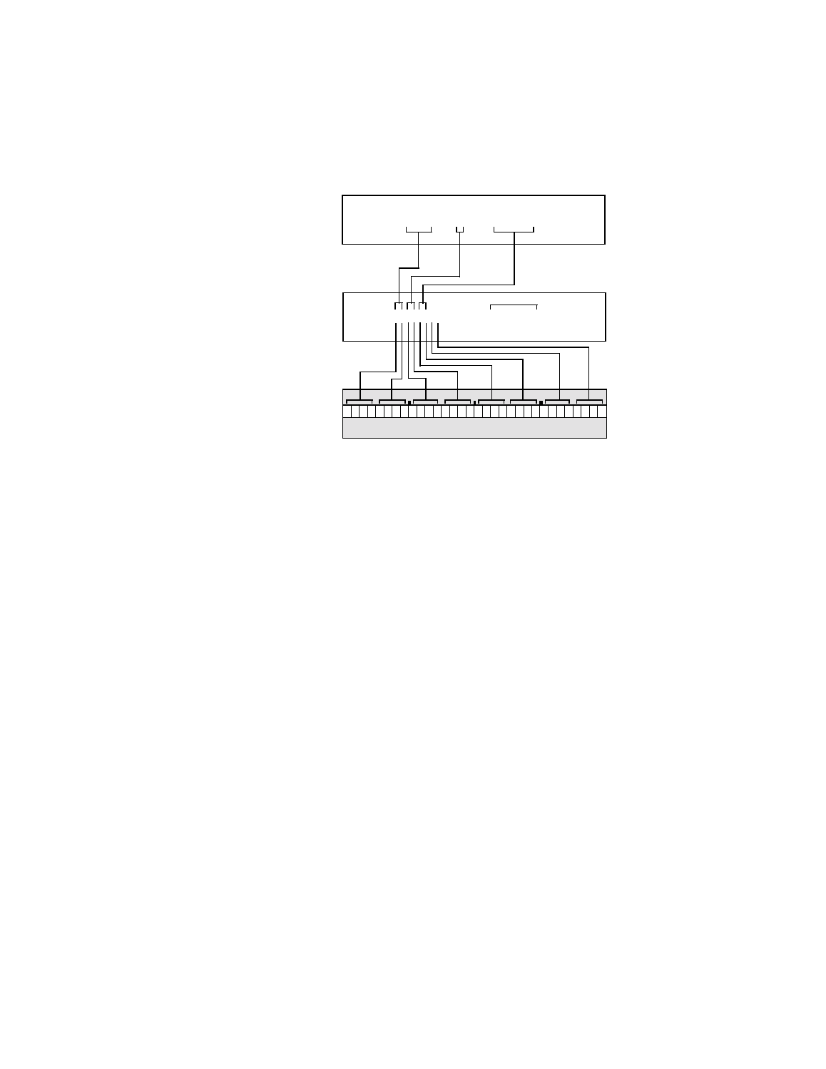
Figure 3.29 Read/Write Instruction Example
3.3.5 Block Move Instruction Example
In this example, shown in
, the processor waits for a valid
phase (indicated by SREQ/ being asserted) and compares it to CMD
phase. If the phase matches, the processor transfers the CDB from the
address represented by the
command_buffer
. In the hexadecimal version
of the first 32-bit word of the instruction, Move is represented by 0x0A,
which translates into binary as an opcode of 00, indicating a Block Move
instruction type. The 0b00 indicates that neither type of indirect
addressing bits are on, 1 indicates that the processing is in the Initiator
role, and 0b010 (Command) is the expected value of the SCSI phase
lines. The command length is six bytes, indicated by 0x06. This length is
loaded into the DBC register.
The bottom portion of the illustration shows the second 32-bit word of the
instruction, defined by
command_buffer.
The Block Move instruction
begins transferring data from this address. It is loaded into the DSPS
register.
NASM
Output
Binary
Instruction
Format
0
1 1 1 0 0
0 0 0 0 0 1 0
0 0 0 0 0 0 0 1 0 0 0 0 0 0 0 0
1
0
0
DCMD Register
DBC Register
78040100
00000000
Move
to SCID
SCSI SCRIPTS
Source Code
1