Figure3.26 memory move instruction part 1, Memory move instruction part 1 – Avago Technologies LSI53C1010 User Manual
Page 115
Instruction Examples
3-75
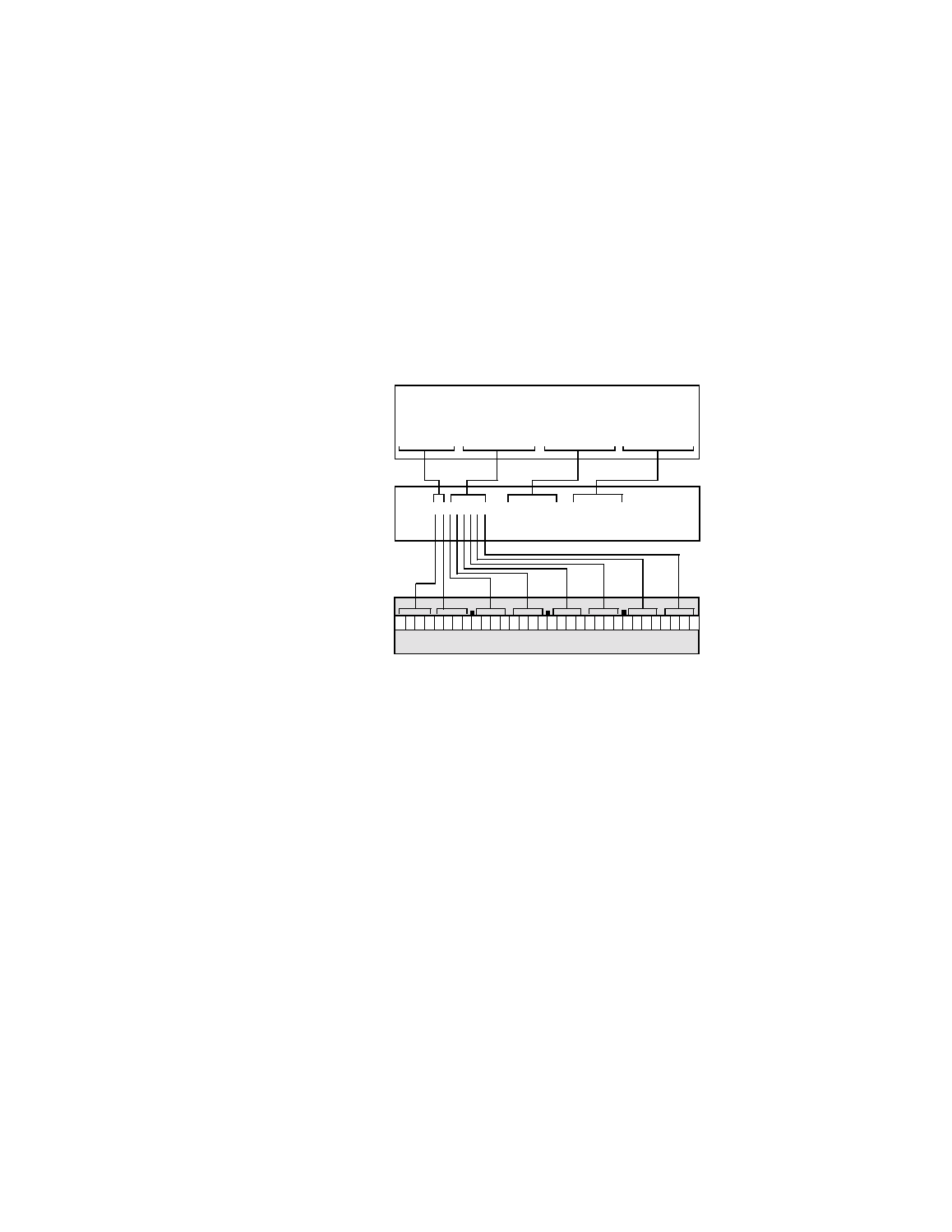
The MEMORY MOVE instruction generates an opcode of C0 for the high
order byte of the instruction. The remaining bits of the DCMD register are
reserved and must be set to zero. The DBC register contains a value of
eight as directed by the translation of the command_length of 0x08.
shows the original SCRIPTS language form of the
instruction, the SCRIPTS compiler output, and the binary form of the first
32-bit word of the instruction.
Figure 3.26 Memory Move Instruction Part 1
shows the Assembler output and the binary form of the
second and third 32-bit words of the Memory Move instruction.
SCSI SCRIPTS
Source Code
NASM
Output
C0000008
00000000
1
0 0 0 0 0
0 0 0 0 0 0 0
0 0 0 0 0 0 0 0 0 0 0 0 1 0 0 0
1
0
0
DCMD Register
DCB Register
Binary
Instruction
Format
ABSOLUTE command_length = 8
RELATIVE rel_buf\
command_buffer = 8{??}\
scratch_buffer = 8{??}
move memory, command_length, command buffer, scratch_buffer
00000008