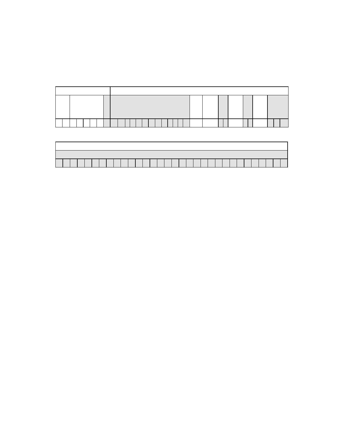
Figure3.19 set format, Set format – Avago Technologies LSI53C1010 User Manual
Page 105

Instruction Descriptions
3-65
Register
Definition(s)
The information listed below describes the DBC and DSPS registers.
Description
The chip asserts the SCSI bus bits requested in the flags field. Currently
four bits are defined, allowing the SCSI ACK/, target role, and ATN/ bits
to be set, as well as the Carry bit in the ALU. Bit 10 is for Carry, bit 9 is
for target, bit 6 is for Acknowledge, and bit 3 is for Attention.
Legal Forms
SET ACK
SET ATN
SET TARGET
SET CARRY
SET ACK and ATN
SET ACK and TARGET
Figure 3.19 SET Format
31 30 29
25 24 23
11
10
9
8 7
6
5 4
3
2
0
DCMD Register
DBC Register
Instr
Type
Opcode
R
R
Set
Clear
Carry
Set/
Clear
Target
Mode
R
Set/
Clear
SACK/
R
Set/
Clear
SATN/
R
0
1
0
1
1
0
0
0
0
0 0 0 0 0 0 0 0 0 0 0 0
x
x
0 0
x
0 0
x
0 0
0
31
0
DSPS Register
R
0
0
0
0
0
0
0
0
0
0
0
0
0
0
0
0
0
0
0
0
0
0
0
0
0
0
0
0
0
0
0
0
Instruction
Type
I/O.
Opcode
Set instruction.
Set/Clear
Carry
1 - sets the Carry bit in the ALU
0 - has no effect
Set/Clear
Target Mode
1 - places the chip into target mode
0 - has no effect
Set/Clear
SACK/
1 - asserts the SCSI acknowledge signal
0 - has no effect
Set/Clear
SATN/
1 - asserts the SCSI attention
0 - has no effect
