Yaskawa Matrix Converter User Manual
Page 71
Digital Operator
3-
3
Note: Except in diagrams, keys are referred to using the key names listed in the above table.
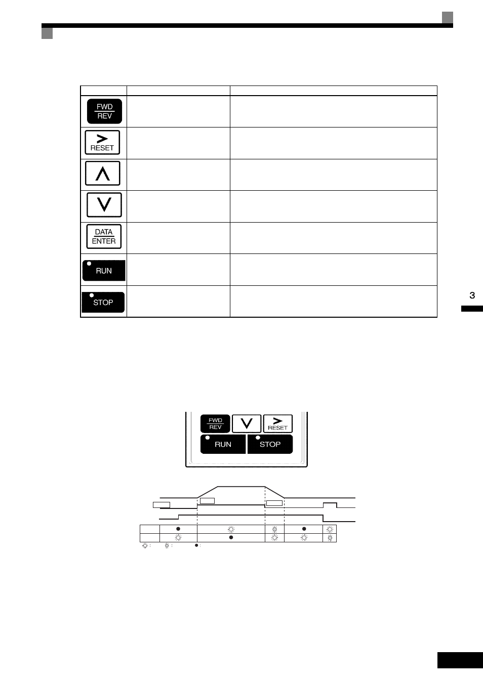
There are indicator LEDs on the upper left of the RUN and STOP keys on the digital operator. These indica-
tors will light and flash to indicate operating status.
An indicator LED on the RUN key will flash and the STOP key LED will light during initial excitation of the
dynamic brake. The relationship between the indicators on the RUN and STOP keys and the MxC status is
shown in the Fig 3.2.
Fig 3.2 RUN and STOP Indicator LEDs
FWD/REV key
Selects the rotation direction of the motor when the MxC is being
operated from the digital operator.
Right arrow/RESET key
Selects the digit to be changed when editing parameter settings. The
selected digit will flash.
Resets a the MxC after a fault as occurred.
Up arrow key
Used to scroll upwards when selecting from a list of parameters.
Increases the setting that appears on the digital operator screen.
Used to move to the next item or data value.
Down arrow key
Used to scroll down when selecting from a list of parameters.
Increases the setting that appears on the digital operator screen.
Used to move to the next item or data value.
DATA/ENTER key
This key is for entering menu items, parameters, and to set values.
Also used to switch from one display to another.
Parameters cannot be changed when Undervoltage (UV) is detected.
RUN key
Sends a run command to have the MxC being operating the motor.
STOP key
Stops MxC operation.
This key can be enabled or disabled when operating from the control
circuit terminal by setting parameter o2-02.
Table 3.1 Key Functions (Continued)
Key
Name
Function
MxC output frequency
Frequency setting
STOP
STOP
RUN
RUN
STOP
Lit
Blinking
Not lit