Related parameters – Yaskawa Matrix Converter User Manual
Page 281

6
-116
Related Parameters
* The default changes if the control method is changed. The values shown in this table are the defaults for Flux Vector Control.
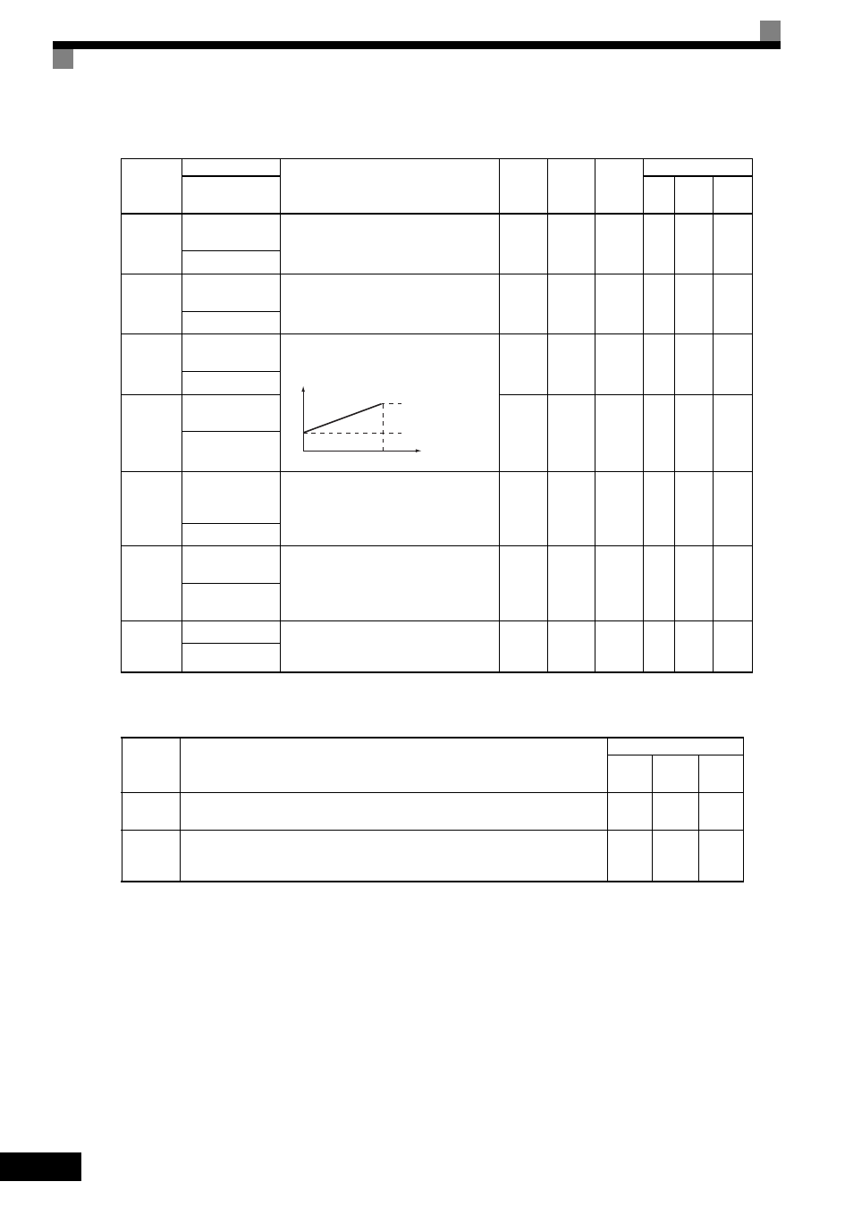
Multi-Function Digital Input Functions (H1-01 to H1-10)
Parameter
Number
Name
Description
Setting
Range
Default
Change
during
Run
Control Methods
Display
V/f
Open
Loop
Vector
Flux
Vector
C5-01
ASR Proportional
Gain 1
Sets the proportional gain of the speed control
loop (ASR).
0.00 to
300.00
20.00
*
Yes
No
No
A
ASR P Gain 1
C5-02
ASR Integral Time
1
Sets the integral time of the speed control
loop (ASR).
0.000 to
10.000
0.500 s
*
Yes
No
No
A
ASR I Time 1
C5-03
ASR Proportional
Gain 2
Sets the speed control gain 2 and integral time
2 of the speed control loop (ASR).
Note: Adjustment is not normally required.
0.00 to
300.00
*
20.00
*
Yes
No
No
A
ASR P Gain 2
C5-04
ASR Integral Time
2
0.000 to
10.000
0.500 s
*
Yes
No
No
A
ASR I Time 2
C5-06
ASR Primary
Delay Time Con-
stant
Sets the filter time constant for the time from
the speed loop to the Torque Command out-
put.
0.000 to
0.500
0.004 s
*
No
No
No
A
ASR Delay Time
C5-07
ASR Gain Switch-
ing Frequency
Sets the frequency for switching between Pro-
portional Gain 1, 2 and Integral Time 1, 2.
0.0 to
120.0
0.0 Hz
No
No
No
A
ASR Gain SW
Freq
C5-08
ASR Integral Limit Sets the ASR integral upper limit and rated
load as a percentage of maximum output fre-
quency (E1-04).
0 to 400
400%
No
No
No
A
ASR I Limit
Set
Value
Function
Control Methods
V/f
Open
Loop
Vector
Flux
Vector
E
Speed control integral reset
Enables switching between PI and P control for the speed control loop.
No
No
Yes
77
Speed control (ASR) proportional gain switch (switching between C5-01 and C5-03)
off: Use proportional gain in C5-01
ON: Use proportional gain in C5-03
No
No
Yes
P, I
0
E1-04
Motor speed (Hz)
P=C5-01
I=C5-02
P=C5-03
I=C5-04
