Yaskawa Matrix Converter User Manual
Page 168
Frequency Reference
6-
3
Inputting the Frequency Reference Using a Voltage Signal (Analog Setting)
When b1-01 is set to 1, the frequency reference can be entered from either control circuit terminal A1 (voltage
input) or control circuit terminal A2 (voltage or current input).
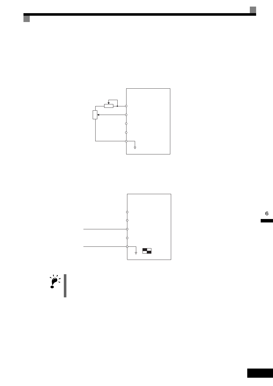
Inputting Master Speed Frequency Reference Only
When using a voltage signal to send the master speed frequency reference, use control circuit terminal A1.
Fig 6.2 Voltage Input for the Master Speed Frequency Reference
When using a current signal to provide the master speed frequency reference, use control circuit terminal A2.
Connect the 0 V lead to terminal A1, set H3-08 to 2 (allows current input for the multi-function analog input
terminal A2 signal level selection), and set H3-09 (Terminal A2 Function Selection) to 0 (add to terminal A1).
Fig 6.3 Current Input for Master Speed Frequency Reference
IMPORTANT
Set pin 2 of DIP switch S1 to the “on” position (towards I) when using current input to terminal A2 (pin 2 deter-
mines the voltage/current). Pin 2 of DIP switch S1 should be set to the “off” position (toward V) when inputting
a voltage to terminal A2. Set H3-08 to the correct setting for the type of input signal being used.
A1
A2
A3
Master speed frequency
reference
(voltage input)
Master speed frequency
reference
(current input)
Auxiliary speed frequency
reference 1
AC Analog common
2 k
Ω
+V Power supply: 15 V,
20 mA
MxC
A1
A2
A3
Master speed frequency
reference
(voltage input)
Master speed frequency
reference
(current input)
Auxiliary speed frequency
reference 1
AC Analog common
+V
4 to 20 mA input
DIP switch
S1
I
V
1
2
Power supply: 15 V,
20 mA
MxC