Torque control, Related parameters – Yaskawa Matrix Converter User Manual
Page 273
6
-108
Torque Control
With Flux Vector Control, the motor’s output torque can be controlled by a torque reference from an analog
input. To carry out the torque control, set d5-01 to 1 or H1- (Multi-function digital input) to 71 for speed
or torque control, and then turn on the contact.
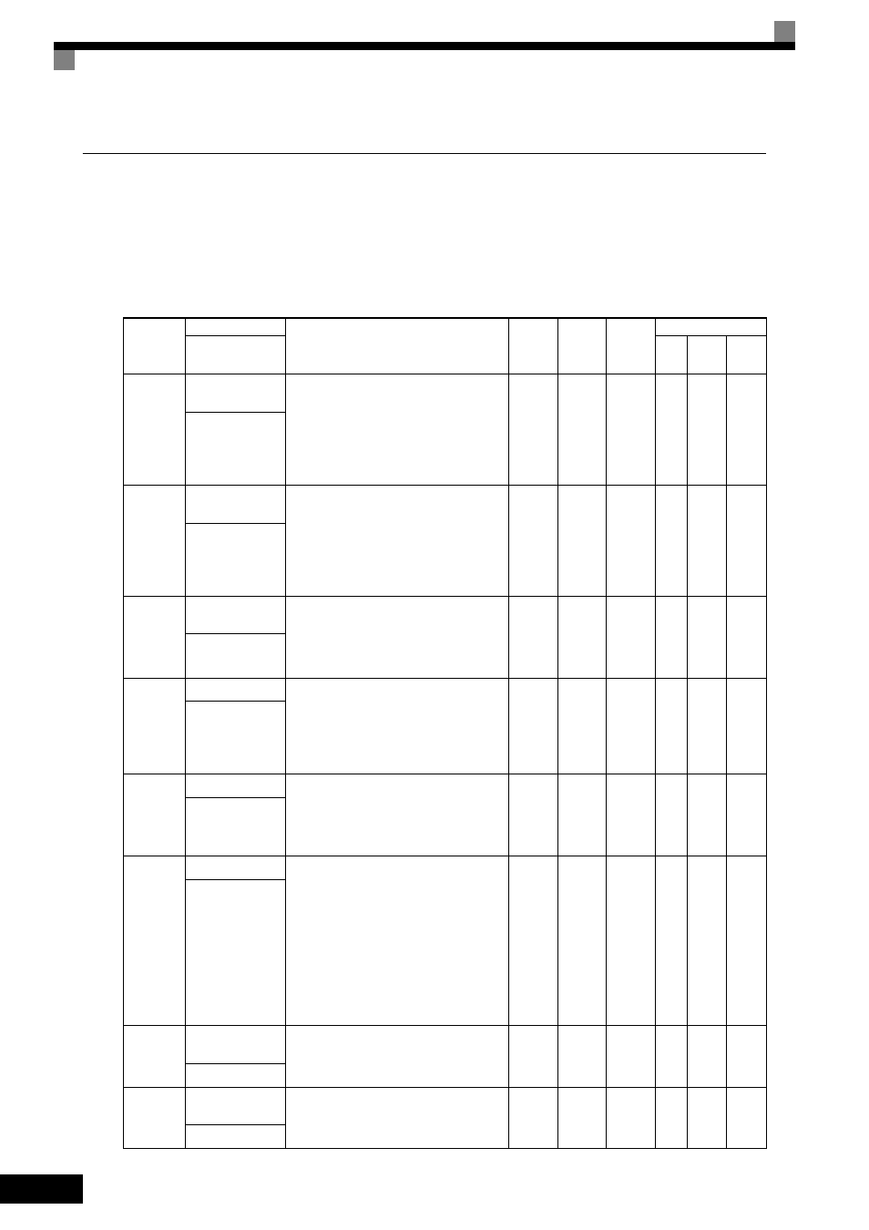
Related Parameters
Parameter
Number
Name
Description
Setting
Range
Default
Change
during
Run
Control Methods
Display
V/f
Open
Loop
Vector
Flux
Vector
d5-01
Torque Control
Selection
0: Speed control (C5-01 to C5-07)
1: Torque control
This function is only available in Flux Vector
Control method. To use the function for
switching between speed and torque control,
set to 0 and set the multi-function input to
“speed/torque control change.”
0 or 1
0
No
No
No
A
Torq Control Sel
d5-02
Torque Reference
Delay Time
Set the torque reference delay time in ms
units.
This function can be used to adjust the noise
of the torque control signal or the responsive-
ness with the host controller. When oscillation
occurs during torque control, increase the set
value.
0 to
1000
0 ms
No
No
No
A
Torq Ref Filter
d5-03
Speed Limit Selec-
tion
Set the speed limit command method for the
torque control method.
1: The analog input limit from a frequency
reference
2: Limited by d5-04 setting values.
1 or 2
1
No
No
No
A
Speed Limit Sel
d5-04
Speed Limit
Set the speed limit during torque control as a
percentage of the maximum output frequency.
This function is enabled when d5-03 is set to
2. Directions are as follows.
+: Run Command direction
-: Run Command opposite direction
-120 to
+120
0%
No
No
No
A
Speed Lmt Value
d5-05
Speed Limit Bias
Set the speed limit bias as a percentage of the
maximum output frequency.
Bias is given to the specified speed limit. It
can be used to adjust the margin for the speed
limit.
0 to 120
10%
No
No
No
A
Speed Lmt Bias
d5-06
PID Output Limit
Set the delay time from inputting the multi-
function input “speed/torque control change”
(from on to off or off to on) until the control is
actually changed, in ms units.
This function is enabled when the multi-func-
tion input “speed/torque control change” is
set. In the speed/torque control switching
timer, the analog inputs hold the values of
when the “speed/torque control change”
changes. Always be sure to allow time for this
process to finish completely.
0 to
1000
0 ms
No
No
No
A
PID Limit
H3-04
Terminal A3 Sig-
nal Level Selection
Sets the signal level of terminal A3.
0: 0 to 10 VDC
1: -10 to +10 VDC
0 or 1
0
No
A
A
A
Term A3 Signal
H3-05
Terminal A3 Func-
tion Selection
Select multi-function analog input function
for terminal A3. Refer to the next page.
0 to 1F
2
No
A
A
A
Terminal A3 Sel