Adjusting frequency references, Adjusting analog frequency references, Related parameters – Yaskawa Matrix Converter User Manual
Page 190
Adjusting Frequency References
6-
25
Adjusting Frequency References
This section explains methods of adjusting frequency references.
Adjusting Analog Frequency References
Gain and bias are among the parameters used to adjust analog inputs.
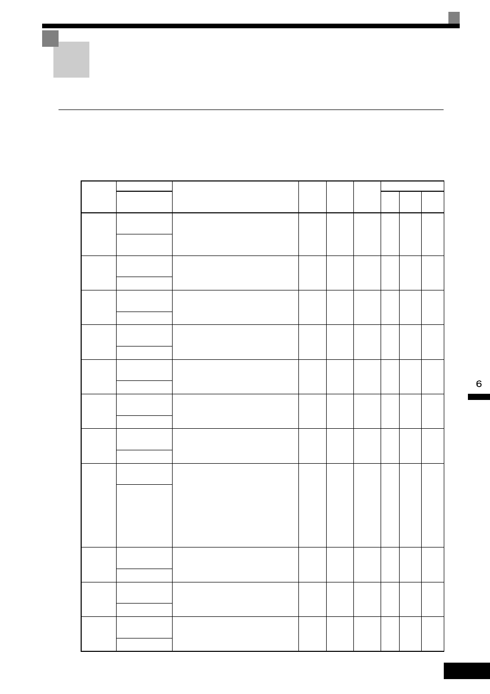
Related Parameters
Parameter
Number
Name
Description
Setting
Range
Default
Change
during
Run
Control Methods
Display
V/f
Open
Loop
Vector
Flux
Vector
H3-01
Terminal A1 Sig-
nal Level Selection
Sets the signal level of terminal A1.
0: 0 to 10VDC
1: -10 to +10VDC
[11-bit plus polarity sign]
0 or 1
0
No
A
A
A
Term A1 Lv1 Sig-
nal
H3-02
Terminal A1 Gain
Setting
Sets the output level when 10 V is input, as a
percentage of the maximum output frequency
(E1-04).
0.0 to
1000.0
100.0%
Yes
A
A
A
Terminal A1 Gain
H3-03
Terminal A1 Bias
Setting
Sets the output level when 0 V is input as a
percentage of the maximum output frequency
(E1-04).
-100.0
to
+100.0
0.0%
Yes
A
A
A
Terminal A1 Bias
H3-04
Terminal A3 Sig-
nal Level Selection
Sets the signal level of terminal A3.
0: 0 to 10 VDC
1: -10 to +10 VDC
0 or 1
0
No
A
A
A
Term A3 Signal
H3-05
Terminal A3 Func-
tion Selection
Select multi-function analog input function
for terminal A3. Refer to the next page.
0 to 1F
2
No
A
A
A
Terminal A3 Sel
H3-06
Terminal A3 Gain
Setting
Sets the output level when 10 V is input.
0.0 to
1000.0
100.0%
Yes
A
A
A
Terminal A3 Gain
H3-07
Terminal A3 Bias
Setting
Sets the frequency reference when 0 V is
input.
-100.0
to
+100.0
0.0%
Yes
A
A
A
Terminal A3 Bias
H3-08
Terminal A2 Sig-
nal Level Selection
Selects the signal level of terminal A2.
0: 0 to 10 VDC (switch S1-2 must be in the
off position).
1: -10 to +10 VDC (switch S1-2 must be in
the off position).
2: 4 to 20 mA (switch S1-2 must be in the on
position)
Note: Switch between current or voltage
inputs by using (S1-2) switch on the
terminal board.
0 to 2
2
No
A
A
A
Term A2 Signal
H3-09
Terminal A2 Func-
tion Selection
Select multi-function analog input function
for terminal A2. Refer to the next table.
0 to 1F
0
No
A
A
A
Terminal A2 Sel
H3-10
Terminal A2 Gain
Setting
Sets the output level when 10V is input.
0.0 to
1000.0
100.0%
Yes
A
A
A
Terminal A2 Gain
H3-11
Terminal A2 Bias
Setting
Sets the output level when 0V is input.
-100.0
to
+100.0
0.0%
Yes
A
A
A
Terminal A2 Bias