Related alarm displays, Related parameters – Yaskawa Matrix Converter User Manual
Page 321
6
-156
Related Alarm Displays
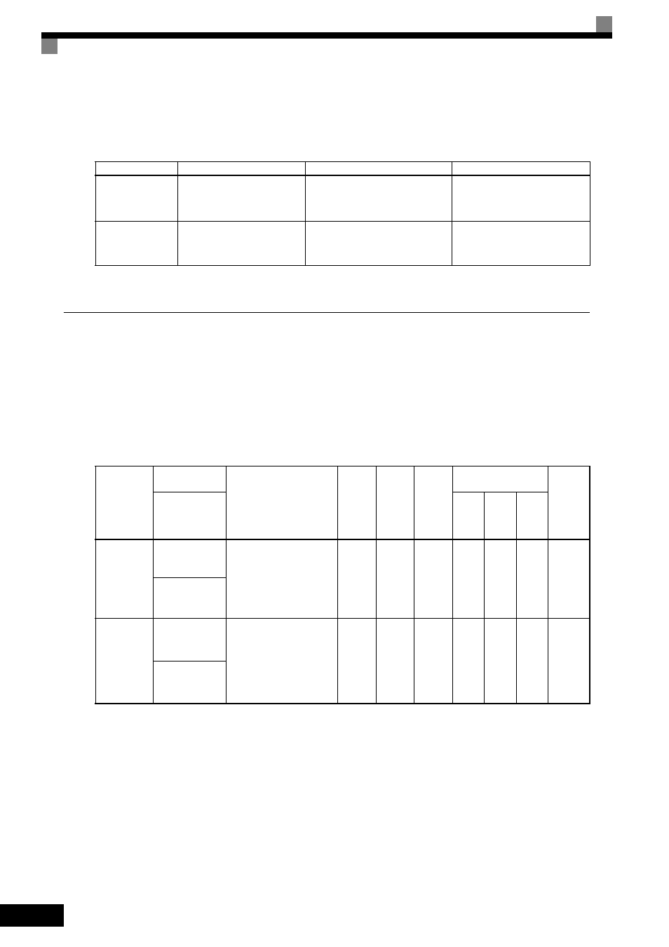
When setting a multi-function contact output H2- to 2F, the alarm is displayed on the digital operator as
shown below.
* Applicable for the Varispeed AC with software versions PRG: 1050 or later.
Settings Required After Replacement of Cooling Fan or Capacitors on
PCB Board
•
Set o2-10 to 0 after replacing the cooling fan.
•
Set o2-18 to 0 after replacing the PCB board.
Refer to Chapter 8 Maintenance and Inspection for the replacement procedure.
Related Parameters
* Applicable for Varispeed AC with software versions PRG: 1050 or later.
Display
Meaning
Probable Causes
Corrective Actions
LT-C
*
(flashing)
Maintenance
Monitor U1-61 has reached
100%.
The capacitors on the PCB board
have reached their estimated
maintenance time period.
Reset parameter o2-18 to “0%”
after replacing the capacitors on
the PCB board.
LT-F
*
(flashing)
Fan Maintenance
Monitor U1-63 has reached
100%.
The cooling fan has reached its
estimated maintenance time
period.
Replace the cooling fan and set
parameter o2-10 to “0H”.
Parameter
Number
Name
Description
Setting
Range
Default
Change
during
Run
Control
Methods
MEMO-
BUS
Register
Display
V/f
Open
Loop
Vector
Flux
Vector
o2-10
*
Fan operation
time setting
Set the initial value of the
fan operation time using
time units.
The operation time
accumulates from the set
value.
0 to
65535
0 hr
No
A
A
A
50EH
Fan ON Time Set
o2-18
*
Capacitor
maintenance
setting
Allows the user to set the
maintenance time for the
capacitors on the PCB board
(U1-61). The user can reset
the accumulated operation
time back to zero, or to some
other desired value.
0 to
150
0%
No
A
A
A
51DH
C MaintenanceSet