Yaskawa Matrix Converter User Manual
Page 122
5
-22
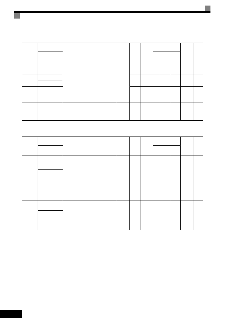
d3: Jump Frequencies
d4: Reference Frequency Hold
Parameter
Number
Name
Description
Setting
Range
Default
Change
during
Run
Control
Methods
MEMO-
BUS
Register
Page
Display
V/f
Open
Loop
Vector
Flux
Vector
d3-01
Jump Frequency 1 Set the center values of the jump frequen-
cies in Hz.
This function is disabled by setting the
jump frequency to 0 Hz. Always ensure
that the following applies:
d3-01
≥ d3-02 ≥ d3-03
Operation in the jump frequency range is
prohibited but during acceleration and
deceleration, speed changes smoothly
without jump.
0.0 to
120.0
0.0 Hz
No
A
A
A
294H
4-17
6-28
Jump Freq 1
d3-02
Jump Frequency 2
0.0 Hz
No
A
A
A
295H
4-17
6-28
Jump Freq 2
d3-03
Jump Frequency 3
0.0 Hz
No
A
A
A
296H
4-17
6-28
Jump Freq 3
d3-04
Jump Frequency
Width
Sets the jump frequency bandwidth in
Hz.
The jump frequency will be the jump fre-
quency
± d3-04.
0.0 to
20.0
1.0 Hz
No
A
A
A
297H
4-17
6-28
Jump Bandwidth
Parameter
Number
Name
Description
Setting
Range
Default
Change
during
Run
Control
Methods
MEMO-
BUS
Register
Page
Display
V/f
Open
Loop
Vector
Flux
Vector
d4-01
Frequency Refer-
ence Hold Func-
tion Selection
Sets whether or not frequencies on hold
will be recorded.
0: Disabled (when operation is stopped
or the power is turned on again starts
at 0.)
1: Enabled (when operation is stopped
or the power is turned on again starts
at the previous hold frequency.)
This function is available when the multi-
function inputs “accel/decel Ramp Hold”
or “up/down” commands are set.
0 or 1
0
No
A
A
A
298H
6-69
MOP Ref Mem-
ory
d4-02
Trim Control
Level
Set the frequency to be added to or sub-
tracted from the analog frequency refer-
ence as a percent, taking the maximum
output frequency to be 100%.
Enabled when the increase (+) speed
command or decrease (-) speed command
is set for a multi-function input.
0 to 100
10%
No
A
A
A
299H
6-73
Trim Control Lvl