Yaskawa Matrix Converter User Manual
Page 318

Elevator and Hoist Type Applications
6-
153
Time Chart
•
Lifting
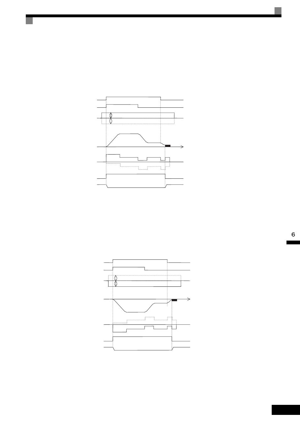
The analog signals corresponding to the load size are input as torque compensation signals from before the
MxC starts until operation stops (default: 10 V/100% torque).
Positive polarity is input for motor loads and negative polarity is input for regenerative loads.
The following diagram shows the time chart for lifting the load.
Fig 6.87 Torque Compensation Time Chart (Lifting)
•
Lowering
In the same way as for lifting, when the torque decreases, the analog signals corresponding to the load size are
input as torque compensation signals from before the MxC starts until operation stops (default: 10 V/100%
torque).
Negative polarity is input for motor loads and positive polarity is input for regenerative loads.
The following diagram shows the time chart for lowering.
Fig 6.88 Torque Compensation Time Chart (Lowering)
off
off
on
UP (Forward)
on
Analog signals corresponding to load size
Same as above
Torque compensation
signal: 0
HIGH/LOW
Output frequency
0
Motor torque
0
off
on
During run 2
OPEN
Holding brake operation
CLOSE
(Motor load: Inputs positive polarity.)
(Regenerative load: Inputs negative polarity.)
t
(Motor load)
(Regenerative load)
Zero-speed control
off
off
on
DOWN (Forward)
on
HIGH/LOW
Output frequency
0
Motor torque
0
off
on
During run 2
OPEN
Holding brake operation
CLOSE
(Regenerative load: Inputs positive polarity.)
(Motor load: Inputs negative polarity.)
t
(Regenerative load)
(Motor load)
Analog signals corresponding to load size
Same as above
Torque compensation
signal: 0
