B2: dc injection braking – Yaskawa Matrix Converter User Manual
Page 110
5
-10
* 1. 0 or 1 for Flux Vector Control.
* 2. Applicable for the Varispeed AC with software versions PRG: 1050 or later.
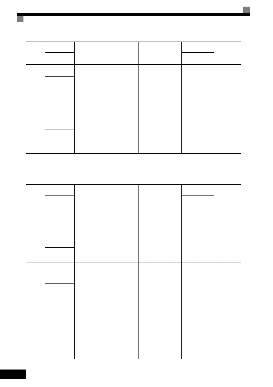
b2: DC Injection Braking
b1-07
Local/Remote
Run Selection
Used to set the operation mode by switch-
ing to the Remote mode using the
LOCAL/REMOTE key.
0: Run signals that are input during
mode switching are disregarded.
(Input Run signals after switching the
mode.)
1: Run signals become effective imme-
diately after switching to the Remote
mode.
0 or 1
0
No
A
A
A
186H
-
LOC/REM RUN
Sel
b1-08
Run Command
Selection During
Program
Used to set an operation interlock in pro-
gramming modes.
0: Cannot operate.
1: Can operate (Disabled when digital
operator is set to select Run Com-
mand (when b1-02 = 0)).
2
*2
:The MENU key is disabled during
run.
0 or 2
*2
0
No
A
A
A
187H
-
RUN CMD at
PRG
Parameter
Number
Name
Description
Setting
Range
Default
Change
during
Run
Control
Methods
MEMO-
BUS
Register
Page
Display
V/f
Open
Loop
Vector
Flux
Vector
b2-01
DC Injection
Braking Start Fre-
quency
Sets the frequency at which DC injection
braking starts when decelerate to stop
(b1-03 = 0) is selected. If b2-01< E1-09,
DC Injection braking starts at E1-09.
Note: Zero Speed restrictions are active
in Flux Vector Mode.
0.0 to
10.0
0.5 Hz
No
A
A
A
189H
6-11
6-123
DCInj Start Freq
b2-02
DC Injection
Braking Current
Sets the DC injection braking current as a
percentage of the MxC rated current.
Note: The DC excitation current is deter-
mined by the setting in E2-03 when
operating in Flux Loop Vector
Control Method.
0 to
100
50%
No
A
A
No
18AH
6-11
6-15
DCInj Current
b2-03
DC Injection
Braking Time/DC
Excitation Time at
Start
Sets the time of DC injection braking at
start in units of 0.01 seconds.
0.00
to
10.00
0.00 s
No
A
A
A
18BH
6-11
6-15
DCInj Time
@Start
b2-04
DC Injection
Braking Time at
Stop
Sets the time length of DC injection brak-
ing at stop in units of 0.01 seconds.
1: When b1-03 = 2, actual DC Injection
time is calculated as follows: (b2-04)
× 10 × (OutputFreq) / (E1-04)
2: When b1-03 = 0, this parameter deter-
mines the amount of time DC Injec-
tion is applied to the motor at the end
of the decel ramp.
3: This should be set to a minimum of
0.50 seconds when using HSB. This
will activate DC injection during the
final portion of HSB and help ensure
that the motor stops completely.
0.00
to
10.00
0.50 s
No
A
A
A
18CH
6-12
DCInj Time
@Stop
Parameter
Number
Name
Description
Setting
Range
Default
Change
during
Run
Control
Methods
MEMO-
BUS
Register
Page
Display
V/f
Open
Loop
Vector
Flux
Vector