Yaskawa Matrix Converter User Manual
Page 159

Parameter Tables
5-
59
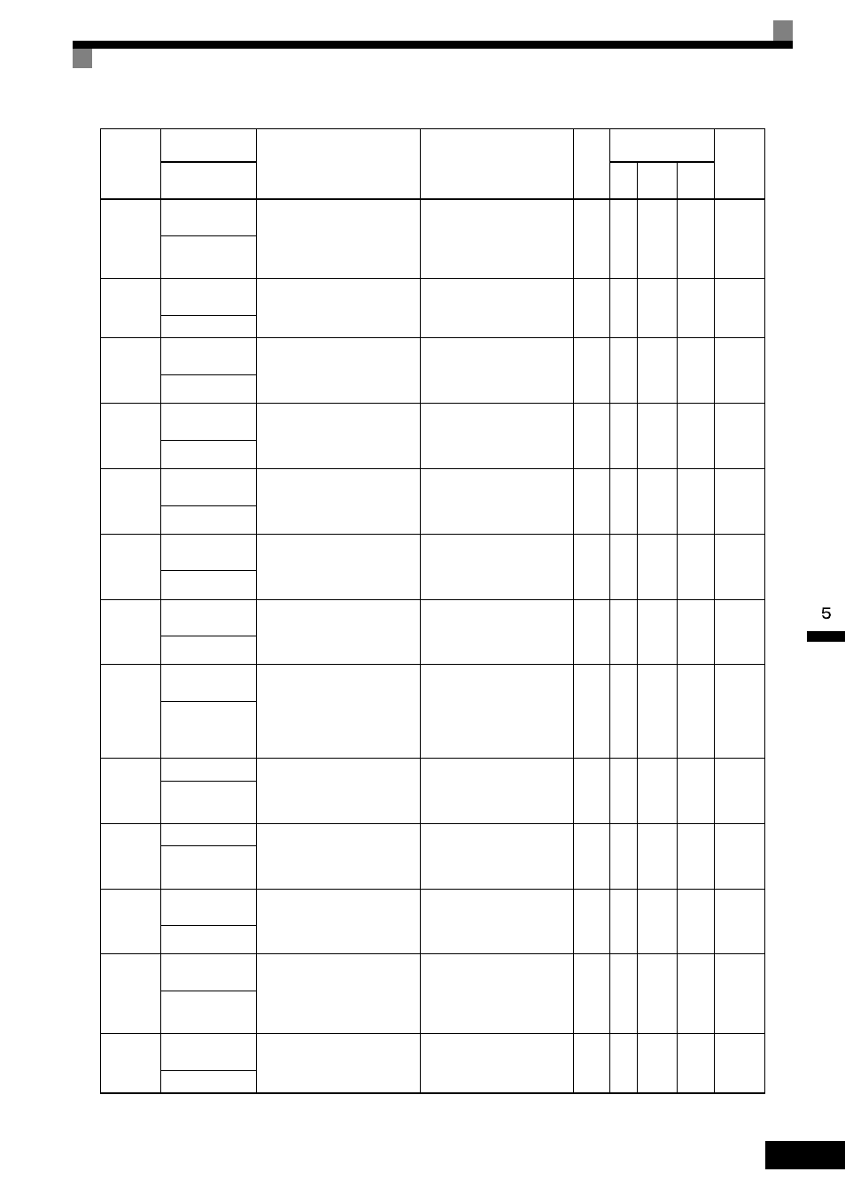
U1-13
Cumulative opera-
tion time
Monitors the total operating time
of the MxC.
The initial value and the operating
time/power on time selection can
be set in o2-07 and o2-08.
No output available
1
hr
A
A
A
4CH
Elapsed Time
U1-14
Software No.
(flash memory)
(Manufacturer’s ID number)
No output available
-
A
A
A
4DH
FLASH ID
U1-15
Terminal A1 input
voltage
Monitors the input voltage of the
voltage frequency reference. An
input of 10 V corresponds to
100%.
10 V: 100% (10 V)
(
−10 V to + 10 V possible)
0.1%
A
A
A
4EH
Term A1 Level
U1-16
Terminal A2 input
voltage
Monitors the input voltage of the
multi-function analog input.
An input of 10 V corresponds to
100%.
10 V: 100% (10 V)
(
−10 V to + 10 V possible)
0.1%
A
A
A
4FH
Term A2 Level
U1-17
Terminal A3 input
voltage
Monitors the input voltage of the
multi-function analog input.
An input of 10 V corresponds to
100%.
10 V: 100% (10 V)
(
−10 V to + 10 V possible)
0.1%
A
A
A
50H
Term A3 Level
U1-18
Motor secondary
current (Iq)
Monitors the calculated value of
the motor secondary current.
The motor rated secondary cur-
rent corresponds to 100%.
10 V: Motor rated secondary
current)
(
−10 V to + 10 V possible)
0.1%
A
A
A
51H
Mot SEC Current
U1-19
Motor exciting
current (Id)
Monitors the calculated value of
the motor excitation current.
The motor rated secondary cur-
rent corresponds to 100%.
10 V: Motor rated secondary
current)
(
−10 V to + 10 V possible)
0.1%
No
A
A
52H
Mot EXC Current
U1-20
Output frequency
after soft-start
Monitors the output frequency
after a soft start.
The frequency given does not
include compensations, such as
slip compensation.
The unit is set in o1-03.
10 V: Max frequency
(
−10 V to + 10 V possible)
0.01
Hz
A
A
A
53H
SFS Output
U1-21
ASR input
Monitors the input to the speed
control loop.
The maximum frequency corre-
sponds to 100%.
10 V: Max frequency
(
−10 V to + 10 V possible)
0.01
%
No
No
A
54H
ASR Input
U1-22
ASR output
Monitors the output from the
speed control loop.
The motor rated secondary cur-
rent corresponds to 100%.
10 V: Motor rated secondary
current)
(
−10 V to + 10 V possible)
0.01
%
No
No
A
55H
ASR Output
U1-24
PID feedback
value
Monitors the feedback value
when PID control is used.
The input for the max frequency
corresponds to 100%.
10 V: Max frequency
(
−10 V to + 10 V possible)
0.01
%
A
A
A
57H
PID Feedback
U1-25
DI-16H2 input sta-
tus
Monitors the reference value from
a DI-16H2 digital reference card.
The value will be displayed in
binary or BCD depending on
parameter F3-01.
No output available
-
A
A
A
58H
DI-16 Reference
U1-26
Output voltage ref-
erence (Vq)
Monitors the MxC internal volt-
age reference for motor secondary
current control.
10 V: 200 VAC (400 VAC)
(
−10 V to + 10 V possible)
0.1
VAC
No
A
A
59H
Voltage Ref (Vq)
Parameter
Number
Name
Description
Output Signal Level
during Multi-Function
Analog Output
Min.
Unit
Control
Methods
MEMO-
BUS
Register
Display
V/f
Open
Loop
Vector
Flux
Vector
